SA380TX DC Track Circuit Monitoring
- Janos Vaczi (Unlicensed)
- Nick Wright (Deactivated)
Introduction
How to set up DC Track Circuit Monitoring on SA380TX data logger.
Steps:
- Setup analogue input channel: set channel name and input sensor
- Setup data acquisition type
GUI
Setting up analogue input channel
First of all you have to set an appropriate name and input sensor for the analogue channel.
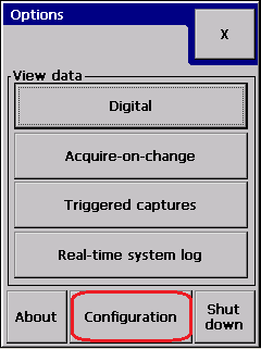
Go to analogue channel configuration:

You have to be authenticated to be able to change the logger configuration:
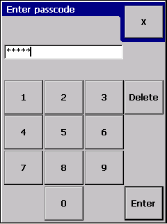 then press enter:
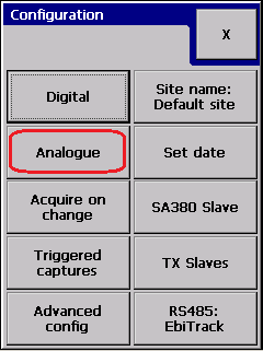
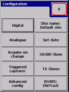
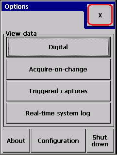
Press "Analogue" on Configuration dialog:
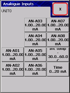
This gets you to the analogue channel selector dialog:
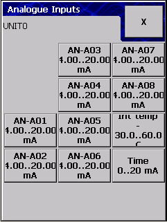
Where you have to select the analogue channel you will want to set up. E.g. select AN-A01:
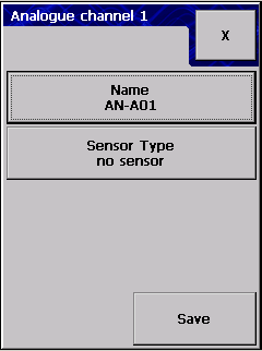 As you can see you can specify the channel name and input sensor for a particular analogue channel.
Let's set the name first:
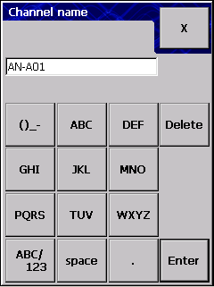 When finished, press Enter.
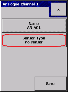
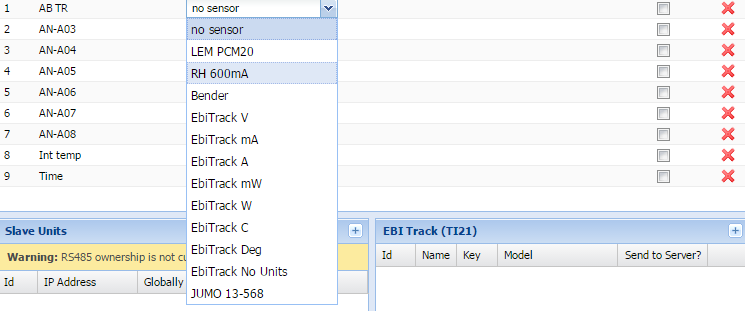
Let's set the sensor next:
This brings you to the sensor selector dialog:
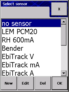 Notice, that we have quite a few pre-defined sensors, it is likely to have one of these installed.
If your sensor is not listed, you can create a new sensor with "New" button. See Creating new input sensor.
Select the appropriate sensor and press the "OK" button to select it for the analogue channel.
 If you are happy with the analogue channel settings, press Save:
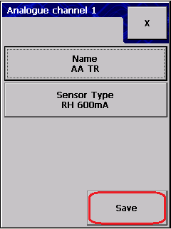
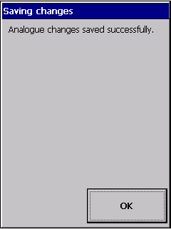
The logger will notify you about the configuration changes:
At this point the logger must be able to read the correct engineering unit samples on the analogue channel. To check it, get back to the Main dialog by pressing the exit "X" button on the dialogs.
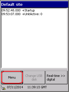
Go to real-time analogue dialog:
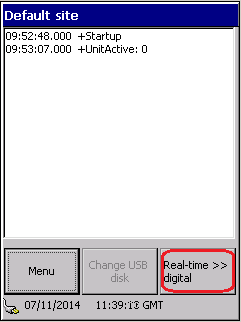
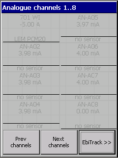
The actual input value can be read on the graph. (Which is -5A now, since we don't have actual sensor connected to the analogue channel.)
Setting up analogue data acquisition
 then enter password and enter:
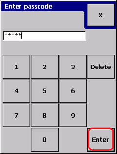
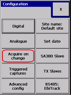
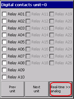
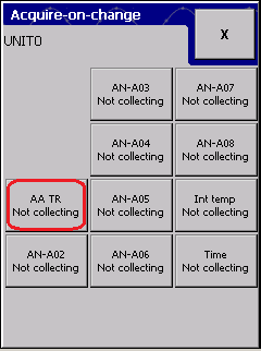
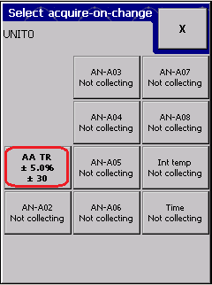
The next selector dialog shows which analogue channels are collecting acquire-on-change measurements:
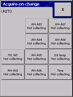
select 701 WI channel:
Brings you to the acquire-on-change configuration dialog:
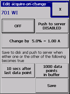
Most importants settings are the ON/OFF and the "Push to server" toggle buttons.
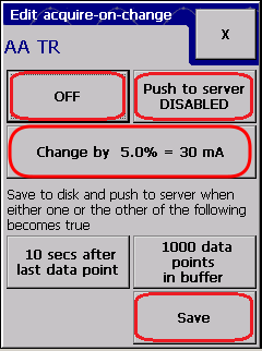
For a typical configuration, set the acquire-on-change threshold to 1% (lower than the default 5%), then toggle push to server and ON/OFF, then save the changes:
Now the data collection method is set for the particular analogue channel. Let's see the collected data:
Go back to the main dialog by closing all the previous screens with the top-right "X" button.
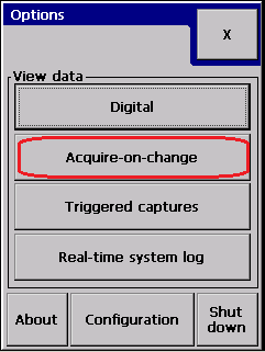
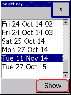
Navigate to acquire-on-change historical data for analogue channel 701 WI:

Web interface
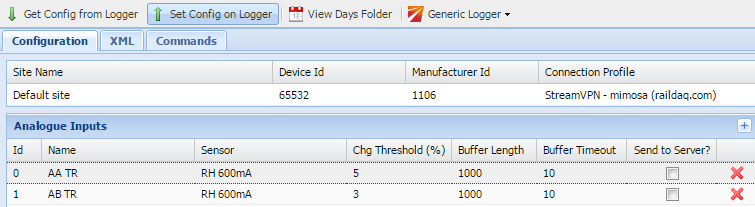
Visiting the web interface we will focus on the Analogue Inputs part of the configuration.
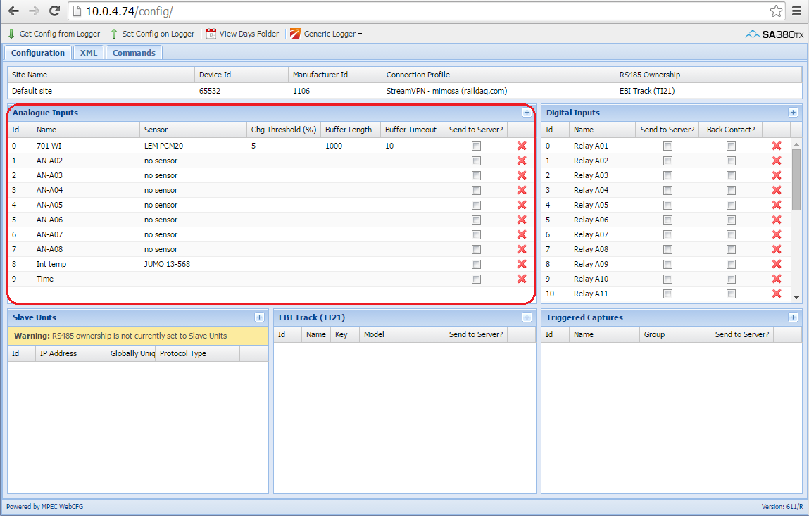
Let's set AN-A02 to a track circuit and enable acquire-on-change on it:
Set name:

Set sensor:
Set acquire-on-change:

Send to logger:
 WebCFG tool sends and retrieves the configuration again:
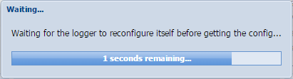
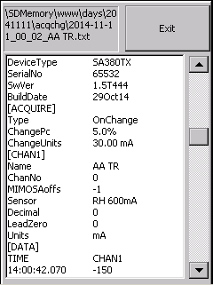
Check the output of the data acquisition:
 Gets to:
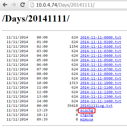
Select today's date:

Open acqchg folder:
Open the new file for AB TR we just set up:
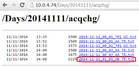
The opened file must contain at least one sample as base acquisition.
Related articles