SA380 series Points monitoring
- Mark Lock
- Janos Vaczi (Unlicensed)
- Mark Beeson (Deactivated)
Overview
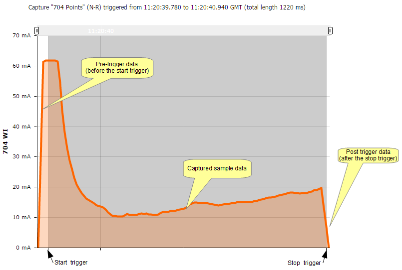
Switches can be monitored on the SA380 TX using digital inputs and analogue channels. With the SA380 TX and SA380 TX-L, this is done using the "trigger capture" mechanism. This data capture method can be applied to any data collection which starts from a known event, such as a relay picking, or a current measurement rising above a pre-determined threshold. The idea behind the trigger capture is to allow a generic configuration for any type of asset where analogue data needs to be captured at maximum sample rate. To this end, the mechanism is open to may uses other than switch monitoring. The general trigger capture consists of two triggers (start and stop) and three data capture phases (pre, during and post), which the following points trace can illustrate:
Common configuration overview
There are several common combinations of switches that are configured. The following examples illustrate these:
- Single PCM 30 (bi directional CT) (analogue start & stop triggers) (Electrical Machines, e.g. M63, HW2000)
- A single PCM30 CT is used.
- Analogue triggers are start and stop data capture on the above channel.
- Single PCM 20 (Command relays - NWR, NWN) (digital start, analogue end) (Clamplocks, electrical or hydraulic)
- A Single CT collects data for motor current.
- Command relays start and stop data capture. (digital triggers)
- Single PCM 20 (Detection relays - NKR, RKR, digital start, digital end) (Clamplocks, electrical or hydraulic)
- A Single CT collects data for motor current.
- Detection relays are used to start and stop data capture. (digital triggers)
- Two PCM 20 - (current triggered) (electrical machines)
- Two CTs are used for data collection, one per direction (Note: see mimosa Id setting below)
- Each CT provides its own trigger for data collection (analogue triggers)
- Single PCM 20 - Valve CTs, CT on N-R and R-N valve (hydraulic machines)
- Analogue triggers from Valve CT.
For a switch, there are generally two transitions which should be recorded, N-R and R-N. The SA380TX allows grouping of capture events
SA380 TX Logger Configuration
The logger is extremely flexible in its configuration and the type of asset that can be monitored, the following sections contain screenshots leading through the setup.
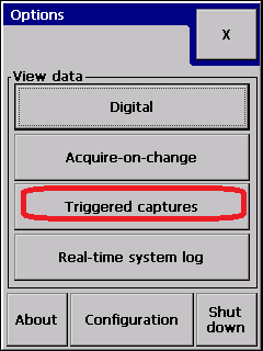
Entering capture configuration
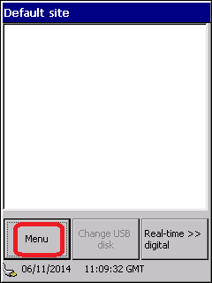
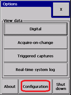
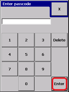
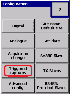
Enter the Trigger capture setup menu:
Create a new capture
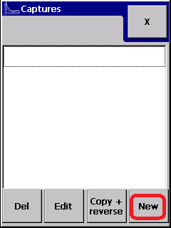
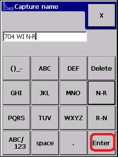
A new capture for a given direction can be created as illustrated below. The "N-R" and "R-N" buttons are provided as a convenience which will allow creation of the alternate swing direction capture semi-automatically if required (see section "creating reverse capture" below.
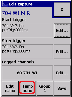
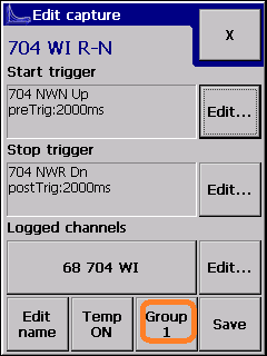
You will now be presented with the following display:
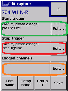
The three highlighted areas are for configuring the start trigger, the stop trigger and the analogue channels to be logged. Selecting "edit" on the right will allowing editing of each one.
Trigger Configuration
Triggers can be analogue or digital and define the starting point and ending point for the capture. The logger will record samples from before the start time "Pre-trigger time" and samples from after the stop trigger "Post-trigger time". It is recommended that these are set to 2000ms (2 seconds) by default, and reduced if it is deemed necessary once a system has settled.
Configuring a digital trigger (start & stop)
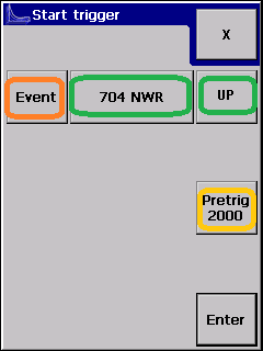
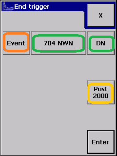
note: The event button will allow you to configure an analogue start or stop trigger.
In the example above, the "704 NWR" and "704 NWN" relays have been selected as the trigger start and end events.
Configuring an analogue trigger (start & stop)
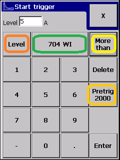
The type of trigger is selected by pressing "level" or "event" (in orange).
The channel to trigger from and the trigger type is shown (in green).
For analogue channels, the trigger threshold is set (pale green) and the trace direction (yellow).
The "Pretrig" value is the time period (measured in milliseconds) specifying the pre-trigger time period.
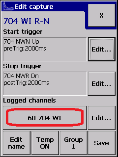
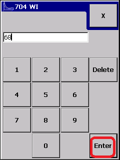
Selecting the analogue channel to collect
The analogue channel to record is selected using the following display:
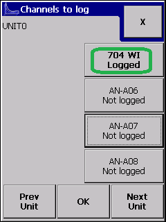
The SA380 TX is capable of logging up to three analogue channels simultaneously in a capture if required. This could be used to capture motor current and hydraulic pressure simultaneously for example. Note: Centrix supports this, it is not supported by Network Rail's II platform for example.
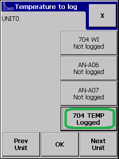
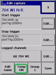
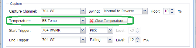
Temperature Recording
An additional reading can be made at the start of the capture (as the start trigger fires) which is reported to the central server as the temperature at the time of the capture. Only one such channel can be recorded. This is set up as illustrated below:
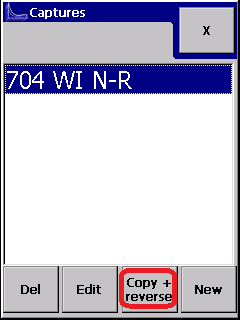
Configuring Reverse Capture
The copy and reverse button can be used to create the capture for the reversed swing. It will bring up the created capture as illustrated.
The start and end triggers have been generated automatically by the logger, and the capture channels copied. The "Group 1" button (orange) is used to allow logical grouping of captures. You should verify that these are correct before proceeding. Where multiple CTs are attached to a set of points it is possible that a different mimosa id is to be recorded for the R-N direction. The following illustrates this.
Updating Mimosa Id
With Centrix, the default channel Id for a capture is predefined to match the loggers physical channel, and it is not necessary to change it. However on the Network Rail II, it is necessary to make sure that N-R and R-N captures, from physically different channels, are logged using the same mimosa offset. Capture channel offsets on the II sit in the range 64-127 (however the logger will not enforce this).

In the "XML" Config tab of the web tool, this change can be accomplished by editing the following fields:
Before
<capt id="2" f="250A_P R-N" push="1" off="1025" captGrpID="2" lu="2019-01-03T08:08:04.710Z">
<startTrig typ="thr" ch="2" a="1" lvl="0.5" t="1"/>
<stopTrig typ="thr" ch="2" a="0" lvl="0.5" t="1"/>
<logChans>
<aipNo off="66">2</aipNo>
</logChans>
</capt>
<capt id="3" f="250A_P N-R" push="1" off="1025" captGrpID="2" lu="2019-01-03T08:08:04.710Z">
<startTrig typ="thr" ch="1" a="1" lvl="0.5" t="1"/>
<stopTrig typ="thr" ch="1" a="0" lvl="0.5" t="1"/>
<logChans>
<aipNo off="65">1</aipNo>
</logChans>
</capt>
After
<capt id="2" f="250A_P R-N" push="1" off="1025" captGrpID="2" lu="2019-01-03T08:08:04.710Z">
<startTrig typ="thr" ch="2" a="1" lvl="0.5" t="1"/>
<stopTrig typ="thr" ch="2" a="0" lvl="0.5" t="1"/>
<logChans>
<aipNo off="65">2</aipNo>
</logChans>
</capt>
<capt id="3" f="250A_P N-R" push="1" off="1025" captGrpID="2" lu="2019-01-03T08:08:04.710Z">
<startTrig typ="thr" ch="1" a="1" lvl="0.5" t="1"/>
<stopTrig typ="thr" ch="1" a="0" lvl="0.5" t="1"/>
<logChans>
<aipNo off="65">1</aipNo>
</logChans>
</capt>
Viewing Capture data
The captured data will be displayed as below.
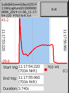
A trace can be inverted by tapping on the legend (above, "703 WI") if requried.
Configuring Captures on the SA380 TX-L
The configuration on the SA380TX-L is performed using the web config tool. Note: The older d-Panel based configuration software is similar and the following guide still applicable.
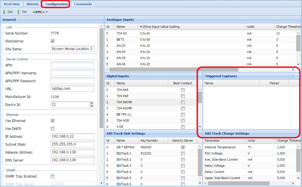
Trigger Captures are displayed in the configuration page as below:
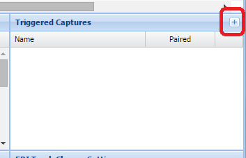
Adding a new capture
Clicking on the "+" symbol will bring up the capture configuration pane
This display (below) is divided into four sections, as illustrated.
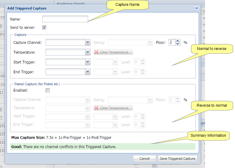
The SA380TX-L is limited to a total of 12 captures, which and if both N-R and R-N swings are to be collected, this will cover 6 ends of points. A paired capture is used when direction information is to be passed to centrix, or the II.
Capture Channel
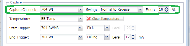
The logger will capture data from the specified channel, using the noise floor value to remove extraneous data from the beginning and end of a trace. The Swing indication is passed to the central server as appropriate.
Temperature Recording
The logger is capable of recording temperature data from any of its analogue channels. This is passed to the central server along with the capture data.
Trigger Configuration
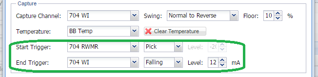
The illustration shows a digital start trigger and an analogue end trigger.
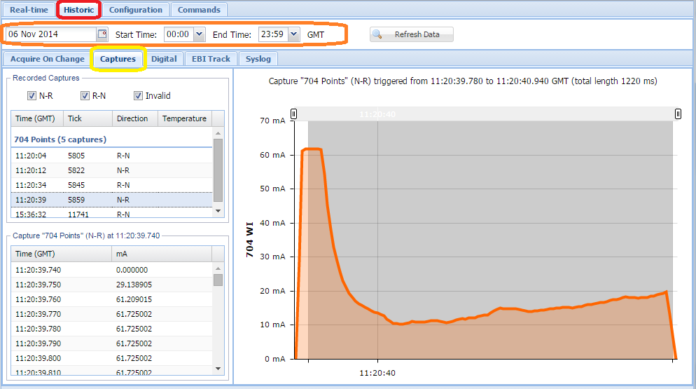
Viewing Capture data stored on the logger
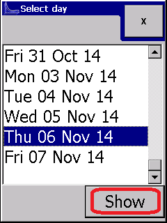
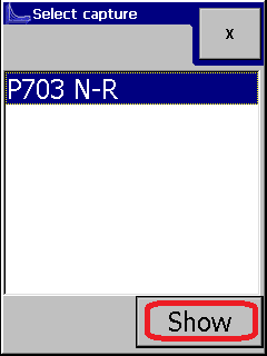
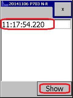
Recorded captures can be viewed on the logger directly, as illustrated below:
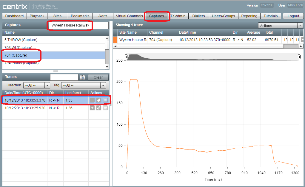
Viewing data on centrix
Clamp lock monitoring on TX-L logger
If motor current and hydraulic pressure are collected on analogue channels like:
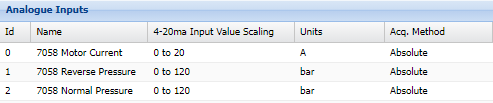
And motor current and hydraulic pressure need to be collected together within the same event then simply set 2 distict capture-pairs to collect either the current either the pressure and make sure the start- and end-triggers are the same! The common trigger will make the two captures being sent as one event.
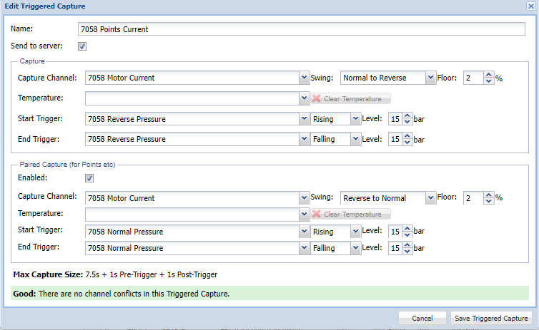
Will collect the motor current and

Will collect the pressure measurements.
Notice that the Start and End Triggers match in Points Current and Points Pressure capture pairs.
Important limitation is that combining captures into one event only works for exactly two captures-pairs! A third capture with the same triggers will be sent as a distinct event.
Related articles