SA380-IT User Guide
- Mark Beeson (Deactivated)
- George Davies
- Janos Vaczi (Unlicensed)
IMPORTANT!
The SA380-IT user guide is presently undergoing an extensive update to reflect the latest advancements in features and operation. Please check this page regularly for updates.

6 Pinnacle Way, Pride Park, Derby, UK, DE24 8ZS
| Sales: | sales@mpec.co.uk |
| General Enquiries: | enquiries@mpec.co.uk |
© Mpec Ltd. 2020 All rights reserved.
No part of this publication may be copied without the prior consent of Mpec.

Contents
1) Product Overview
2) Safety Information
2.1) Explanation of Symbols
2.2) Intended Use
2.3) Warranty & Liability
2.4) Personnel
2.5) Handling Hazards
2.6) Safe Installation
Detailed wiring instructions can be found in section 3. The purpose of this section is to reinforce critical safety information.
Please note the following important wiring information:
| No. | Safe? | Notes |
|---|---|---|
| 1 | Yes | Connection of supply to "circuit 1" input using "Hi Z" supply output |
| 2 | Yes | Correct fitment of resistive cables. Connection to circuit bus-bar is via an independent fuse. |
| 3 | Yes | Correct fitment of resistive cables. No independent fuse is required for safe operation |
| 4 | No | No resistive cable fitted. Circuit vulnerable to short-circuit faults. |
| 5 | No | Incorrect fitment of resistive cable. Circuit vulnerable to through-crimp failure. |

| No. | Safe? | Notes |
|---|---|---|
| 1 | No | Do not "common" circuits. N50(E) and N50(I) isolation compromised. |
| 2 | No | Ensure correct connector position alignment. N120 and B24 isolation compromised. |

Not following this advice risks:
- Circumvention if the inter-isolation of monitored circuits.
- Short circuit of individual monitored circuits.
Electric shock.
The Functional Earth and Loop Earth must be connected to suitable earthing points using separate wires.
- It is preferable to use independent earthing points for loop earth and functional earth connections.
- It is tolerable to use a common earthing point if provision of a secondary earthing point is prohibitive.
- It is not acceptable to simply strap Functional Earth to Loop Earth.
An ineffective Earth Loop circuit is unable to verify correct connection of the SA380-IT, hence insulation readings may be incorrect.
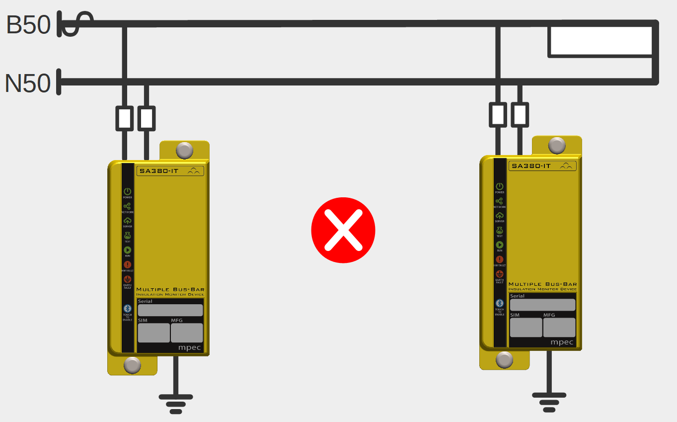
Only one insulation monitoring device may be used on a single interconnected circuit. Installation of additional monitoring devices will cause each device to "fight" the other, resulting in incorrect readings on both devices.
Check that the factory set earth loop and insulation resistance alarm levels are correct for your application. (See section 4.4.10)

Nominal voltage is used to drive important safety features of the SA380-IT
It is important that this is set correctly.
The Ethernet port is sensitive to electrical surges:
- Additional surge protection must be fitted if the port is to be used continuously for data transmission using:
- A dedicated Ethernet surge protection device, or
- Use of screened Ethernet cable

- Surge protection is not required for temporary configuration and diagnostics activities.
Power Supply
The SA380-IT can be purchased with two alternate power supply options:
- 110 V AC
- 12 V DC
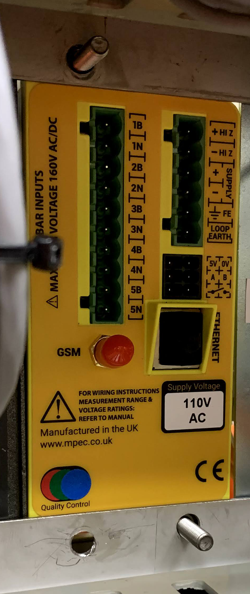
The device power supply voltage is clearly indicated on the rear of the device.
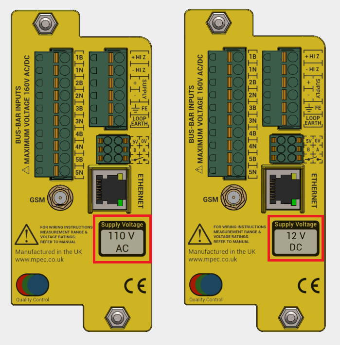
Connection of a 110 V AC supply to 12 V DC units will render the device inoperable!
Limitations of use in the United Kingdom

The following restrictions upon use must be observed when the SA380-IT is deployed on UK rail infrastructure:
Never attempt to power the SA380-IT from a DC power source
Never attempt to wire any conductors from differing monitored circuits into the same input channel.
Users in other countries may disregard these warnings.
No residual hazards have been identified if the above advice is not followed, but these practices are against UK railway policy.
Ensure that you have exhausted all fault finding tasks prior to manually resetting any device interlock (see section 5.2 and section 4.4.5).
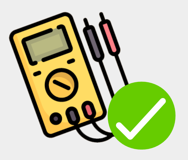
It is wise to conduct a manual insulation test on monitored circuits prior to, and after installation. This will help verify correct installation of the measurement circuit wiring during commissioning.
A manual continuity test between Functional Earth and Loop Earth connections after installation will help verify correct installation of the earth-loop circuit wiring during commissioning.
When conducting manual insulation testing on monitored circuits after commissioning, the SA380-IT must be either:
- Prevented from attempting measurement (see section 4.4.5).
- Physically disconnected from the monitored circuit.
- Powered-down.
Failure to do so will result in incorrect readings.
3) Installation
3.1) Parts and Tools Required
Ensure you have the following parts and tools to hand prior to installation. Tools are not supplied.
Please note that the cable terminations to the "live" system, and cable markers are not supplied. This is because of the wide variety of methods of termination to power supply busbars encountered. Please ensure you have an adequate supply of appropriate terminations and a suitable master fuse prior to installation.
Parts
SA380-IT Insulation Monitoring Unit |
| |
| NA |
| 1 |
M5 A2 Stainless Steel Washers for device fitment |
| |
| NA |
| 2 |
M5 A2 Stainless Steel Nuts for device fitment |
| |
| NA |
| 2 |
GSM Antenna For cellular network communication |
| |
| Mpec Part No: MIS-PAN-PUK/LPAB |
| 0 - 1 |
Shrouded Ferrule crimps 0.75 mm2 10 mm crimps for 0.75 mm2 wire terminations |
| |
| WEIDMULLER H0,75/16 W SV INSULATED FERULE. P/N: 9025860000 |
| 4 - 16 |
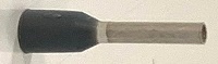
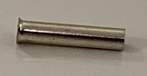
Uninsulated Ferrule Crimps 10 mm crimps for 1.5 mm2 wire terminations |
| |
| WEIDMULLER H1,5/10 UNINSULATED FERULE. P/N: 0186500000 |
| 2 |
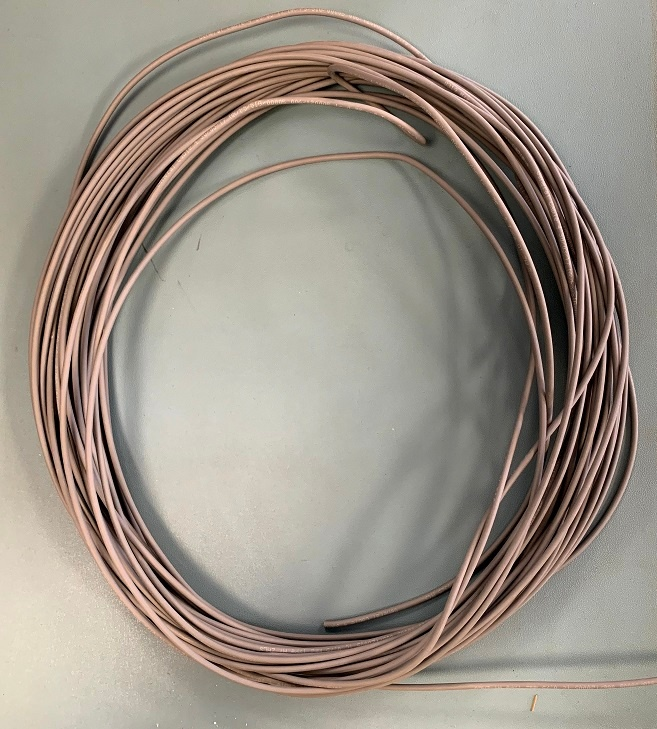
0.75 mm2 stranded single core cable For power supply and monitored circuit connections |
| |
| ELAND Grey NR Approved A1 0.75mm 1 Core Cable - A5RA1010075GR |
| 0 - 30m |
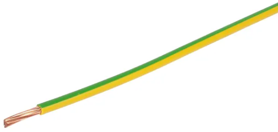
1.5 mm2 stranded single core "earth" cable For primary and "loop" earth connections |
| |
| ELAND Single Core, Stranded, 1.5 mm sq. CSA, Yellow / Green - A2TGY0015 |
| 0 - 3m |
Resistive Cable For safe connection to monitored circuits |
| |
| Mpec Part No: COM-IT-RESCAB |
| 0 - 10 |
Cable Markers For termination identification. | No Image | |
| Quantity, type and requirement customer dependent |
| ?? |
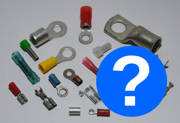
"Live End" Circuit Termination Crimps For terminating power supply, monitored circuits and earth connections | No Image | |
| Quantity, type and requirement customer dependent |
| 4 - 14 |
Main Fuse T2A Fuse Main fuse for device power connection. | No Image | |
| Type and requirement customer dependent |
| 1 |
Additional Monitored Circuit Fuses Optional fuses fitted in the positive leg of monitored circuits | No Image | |
| Type and requirement customer dependent |
| 0-5 |
Screened Ethernet Cable For fixed IP network communication. |
| |
| RS Blue Cat6 Cable S/FTP PVC Male RJ45/Male RJ45, 10m - 411-306 |
| 0 - 1 |
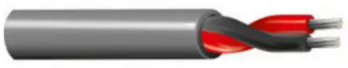
0.5 mm2 Twisted Pair Cable For RS485 serial data connection. |
| |
| RS Belden 1 Pair Industrial Cable 0.5 mm² - 382-7189 |
| 0 - 1 |
Shrouded Ferrule crimps 0.5 mm2 For RS485 serial data connection. |
| |
| WEIDMULLER H0,5/14D W INSULATED FERRULE. PN. 9019010000 |
| 0 - 2 |


Tools
| 8 mm Nut driver or 8 mm spanner | For securing fixing nuts |
| WERA 190 i VDE Insulated Nut-driver - 05005315001 |
|
| Square Wire End Ferrule Crimper | For crimping wire ferrules for correct wire termination to the SA380-IT device |
| WEIDMULLER PZ 10 SQR WIRE END FERULE CRIMPER. P/N: 1445080000 |
|
| Insulated 2.5 mm Flat-blade Screwdriver | For removing wires from the SA380-IT spring-cage connectors |
| WERA 160 i VDE Screwdriver - 05006105001 |
|
| Wire Stripper / Cutter | For preparing wires for termination |
| WEIDMULLER STRIPAX 16 ZERT |
|
| Red Crimping Tool | For crimping the 0.75 mm2 stranded single core cable to the resistive-cable modules |
| TE - Premium Crimp Tooling - PIDG - 409775-1 |
|
| iPhone | For local set-up and diagnostics |
| Mpec Part No: COM-IT-CD |
|
| Laptop + Ethernet Cable | For local set-up and diagnostics if an iPhone is not available |
System Requirements:
|
|
| Additional Crimping / Fixing Tool(s) | For crimping and connecting power supply, monitored circuits and earth connections to the "live" system to be monitored. |
| Type and requirement customer dependent | No Image |
| Drill + 12 mm Drill bit | Maybe required to route the antenna to the exterior of the installation point. |
| Type and requirement customer dependent | No Image |


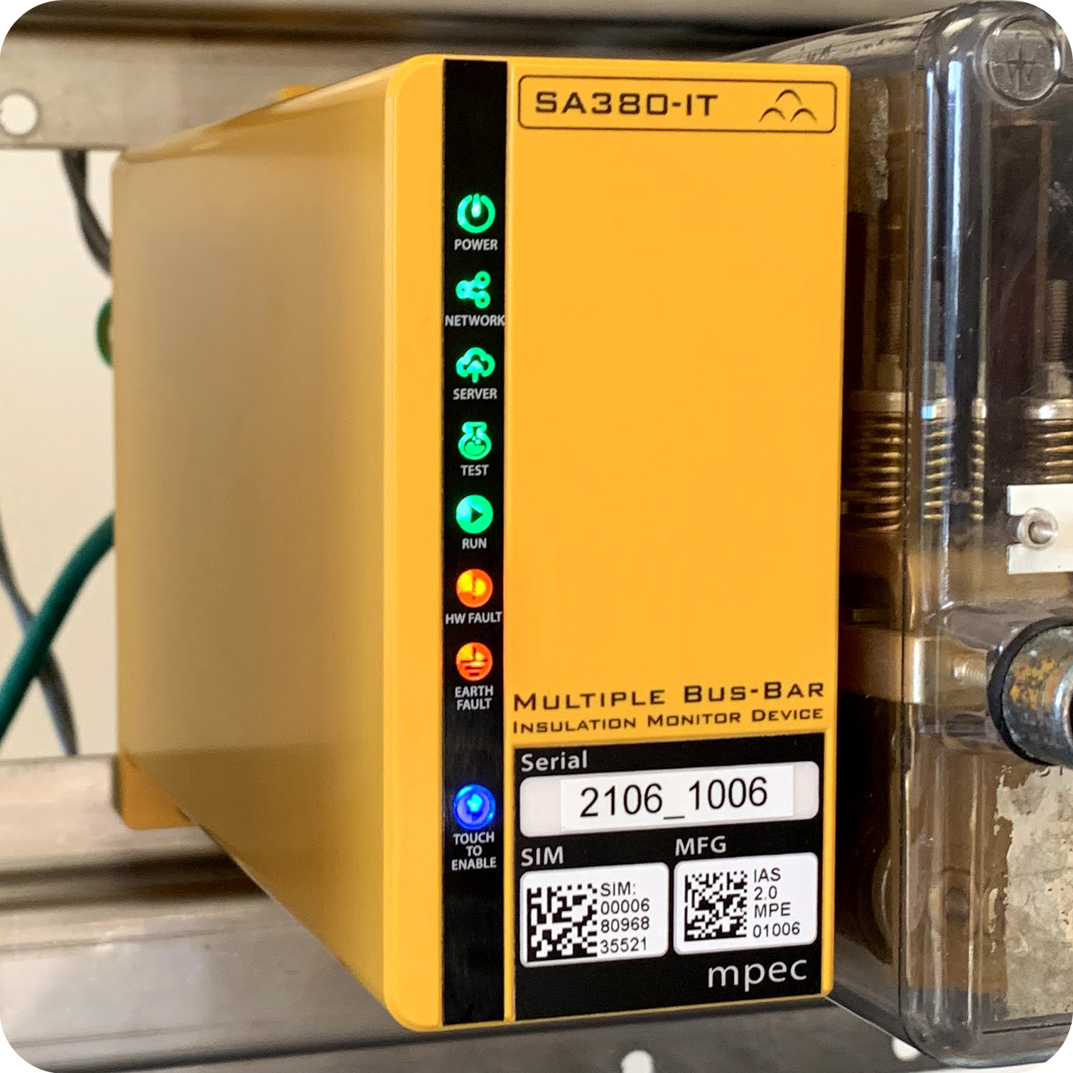
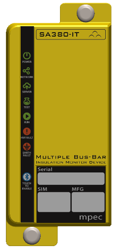
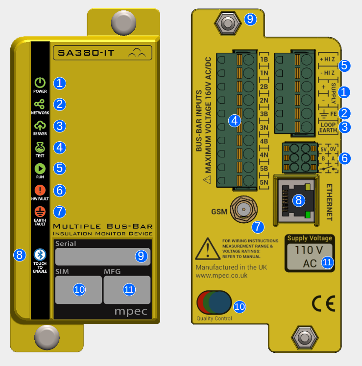
3.2) SA380-IT Layout
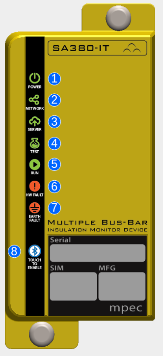
| Front Panel | ||
|---|---|---|
| No. | Name | Description |
| 1 | Power | Lit if the SA380-IT has main power |
| 2 | Network | Lit if the SA380-IT is connected to the GSM network |
| 3 | Server | Lit if the SA380-IT is connected to an Asset Management Server System |
| 4 | Test | Illuminates during self-test. |
| 5 | Run | Pulsates if the software is running. |
| 6 | HW Fault | Indicates a hardware or earth loop integrity problem |
| 7 | Earth Fault | Indicates the presence of an insulation fault |
| 8 | Bluetooth | Combined Indicator and touch-sensitive button. Touch to enable bluetooth functionality. Extinguished: Bluetooth disabled. Blinking: Awaiting pairing. Lit: Paired and active |
| 9 | Serial Number | Easy-read serial number of the device. |
| 10 | SIM Serial | Serial number of the built-in SIM |
| 11 | MFG Serial | Full serial number of the device. |
| Rear Panel | ||
|---|---|---|
| No. | Name | Description |
| 1 | Supply | Power supply to the SA380-IT |
| 2 | Functional Earth | Common Earth point for all device measurement |
| 3 | Loop Earth | Secondary Earth point for earth continuity measurement |
| 4 | Monitored Circuits | Connections for the IT circuits that require insulation monitoring |
| 5 | HiZ Outputs | A simple means of safely monitoring the insulation of the supply circuit. |
| 6 | Auxiliary Outputs | I/O to other devices and alarm circuits |
| 7 | GSM Antenna | Facilitates GSM connection to an Enterprise Asset Management System |
| 8 | Ethernet Jack | Allows local configuration and diagnostics, or Ethernet connection to an Enterprise Asset Management System |
| 9 | Fixing Stud | M5 mounting studs to fit BR930 / Q Style relay mountings. Brackets are available to allow alternate mounting arrangements |
| 10 | Quality Control | Device had undergone voltage withstand, calibration and inspection processes. |
| 11 | Supply Voltage | 110 V AC or 12 V DC supply indication. |
3.3) Typical Circuit
Use the typical circuit below to aid in the production of reference designs.
Please ensure that you do however read and observe the complete installation instructions.

3.4) Pre-Installation
The following precautions must be taken during storage and transportation:
- Protection from prolonged rainfall.
- Protection from immersion in water.
- Ensure that the storage temperature is not exceeded.
- Protection against crushing
Damaged enclosures can expose hazardous voltages and nullifies the SA380-IT Ingress-Protection.
Prolonged exposure to, or immersion in water exceeds the SA380-IT Ingress-Protection rating. Under such conditions dielectric withstand voltages cannot be guaranteed.
Never install or energise an SA380-IT that appears to be either physically damaged or suffering from water ingress.
It is wise to conduct a manual insulation test on monitored circuits both prior to, and after installation, but before energising the SA380-IT. This will help verify correct installation of the measurement circuit wiring.
A manual continuity test between Functional Earth and Loop Earth connections after installation, but before energising SA380-IT will help verify correct installation of the earth-loop circuit wiring.
3.5) Fitting
| Parts | |
|---|---|
| SA380-IT |
|
| M5 A2 Stainless Steel Washers |
|
| M5 A2 Stainless Steel Nuts |
|
| Tools | |
| 8 mm Nut driver or 8 mm spanner |
|
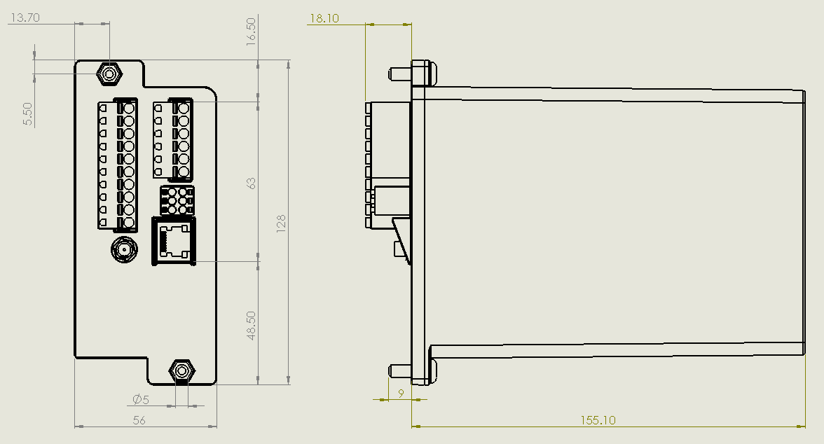
- Mounting studs are arranged to fit relay racking spaced for BR930 or "Q Style" relays
- Exact mounting stud spacings can be found in the specification section of the user guide
- Hinged wall brackets and adaptor brackets are available to accommodate alternative mounting arrangements. Contact Mpec.
- Offer the SA380-IT device up to the relay racking
- Slide the washers over the mounting studs
- Fit the nuts and tighten using the nut-driver / spanner.
- Inspect that the spring washers are not fully compressed (over-tightened). Optimum tightening torque is 1.0 Nm-1
- The SA380-IT should feel secure and free of play or wobble.
3.6) Termination of SA380-IT Wiring
| Parts | |
|---|---|
| 0.75 mm2 Shrouded Ferrule crimps |
|
| Uninsulated Ferrule Crimps |
|
| 0.75 mm2 stranded single core cable |
|
| 1.5 mm2 stranded single core "earth" cable |
|
| Cable Markers | No Image |
| Tools | |
| Square Wire End Ferrule Crimper |
|
| Wire Stripper / Cutter |
|
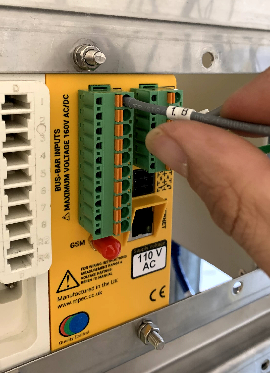
All wire terminations into the SA380-IT use require wire insertion into spring-clamp connectors at the rear of the device.
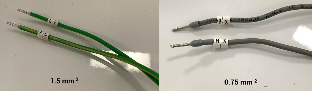
- All wire ends must be correctly terminated with a ferrule crimp of the appropriate size.
- The ferrules must be compressed using a square-end ferrule crimping tool.
Affix cable marker beads if required.
Strip 12 mm of outer insulation from the end of the cable
Select the correct crimp:
- 0.75 mm2 cable: WEIDMULLER H0,75/16 W SV INSULATED FERULE. P/N: 9025860000
- 1.5 mm2 cable: WEIDMULLER H1,5/10 UNINSULATED FERULE. P/N: 0186500000
Fit the crimp over the wire end, ensuring the crimps fit flush against the cable insulation.
Compress the crimp using a square-ended ferrule crimping tool
Inspect the crimp
- No loose strands
- No excessive copper exposed at either crimp end.
- Sufficient exposed wire held firm by the crimp
- An even square profile.
- Ferrule is secure
To insert a wire into the spring-cage connector
- Simply press the ferrule fully-home into the spring cage plug
- Pull at the wire, if secure the wire will not move.
- No exposed metal should be visible if wire correctly crimped and pushed fully-home into the connector.
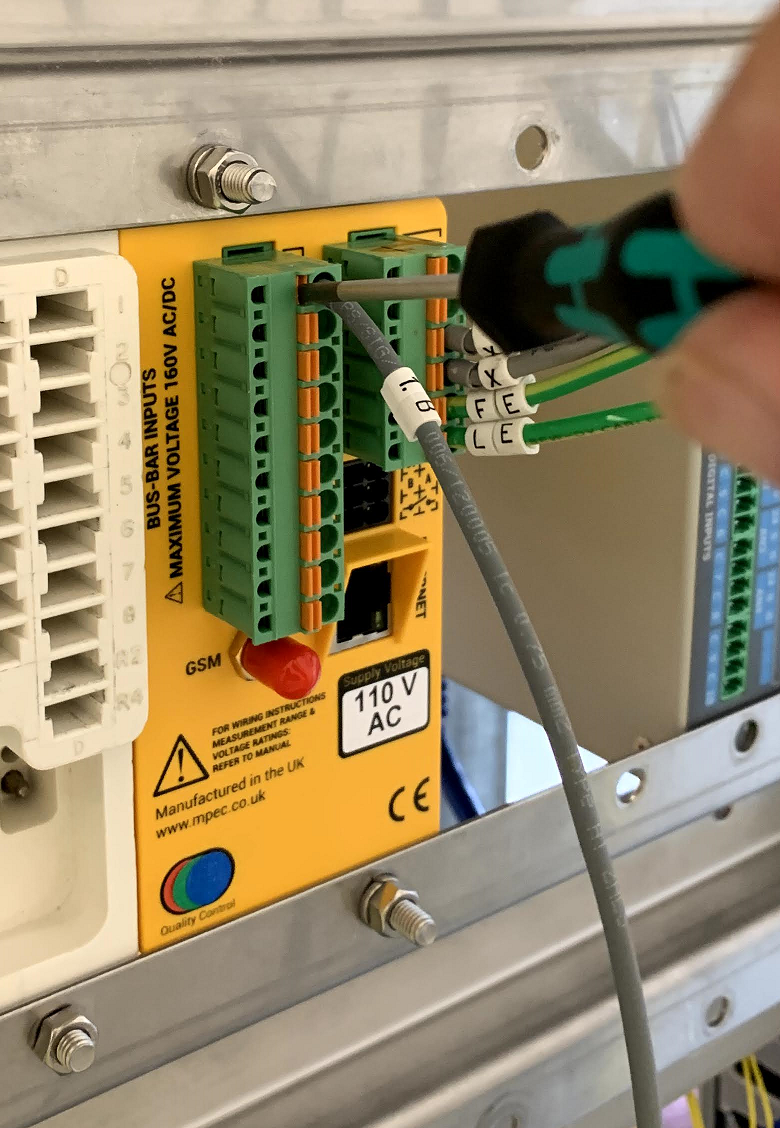
To remove a wire from the spring-cage connector
- Press the blade of an insulated flat-bladed screwdriver into the release latch
- Withdraw to wire
3.7) Wiring the Power Supply
| Parts | |
|---|---|
| 0.75 mm2 stranded single core cable |
|
| 0.75 mm2 Shrouded Ferrule crimps |
|
| Cable Markers | No Image |
| "Live End" Circuit Termination Crimps | No Image |
| Main Fuse T2A Fuse | No Image |
| Tools | |
| Square Wire End Ferrule Crimper |
|
| Wire Stripper / Cutter |
|
| Additional Crimping / Fixing Tool(s) | No Image |
Power Supply
The SA380-IT can be purchased with two alternate power supply options:
- 110 V AC
- 12 V DC
The device power supply voltage is clearly indicated on the rear of the device.

Connection of a 110 V AC supply to 12 V DC units will render the device inoperable!
Limitations of use in the United Kingdom
The following restrictions upon use must be observed when the SA380-IT is deployed on UK rail infrastructure:
Never attempt to power the SA380-IT from a DC power source
Users in other countries may disregard these warnings.
No residual hazards have been identified if the above advice is not followed, but these practices are against UK railway policy.
"Live end" crimp types and fuse-holder sizes vary, therefore no specific crimps or fuses are recommended.
Wire the "+" and "-" supply terminals as shown:
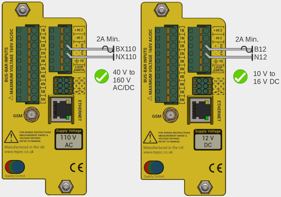
Do not use resistive cables
Supply Voltage Ranges:
Labelled Voltage | Min. V | Max. V |
|---|---|---|
| 110 V AC | 40 AC/DC | 160 AC/DC |
| 12 V DC | 10 DC | 16 DC |
Use appropriate cable markers, crimps & crimp tools for the live terminations.
Use appropriate tools to to affix the live cables their terminations.
The "positive" leg of the supply circuit must be fitted with a type "T2A" (2 Amp Slow-Blow fuse) of the appropriate size.
It is recommended to not apply power to the device until all installation steps are complete.
3.8) Wiring the Earth Loop
| Parts | |
|---|---|
| 1.5 mm2 stranded single core "earth" cable |
|
| Uninsulated Ferrule Crimps |
|
| Cable Markers | No Image |
| "Live End" Circuit Termination Crimps | No Image |
| Tools | |
| Square Wire End Ferrule Crimper |
|
| Wire Stripper / Cutter |
|
| Additional Crimping / Fixing Tool(s) | No Image |


"Earth bus-bar" crimp types will vary, therefore no specific crimps are recommended.
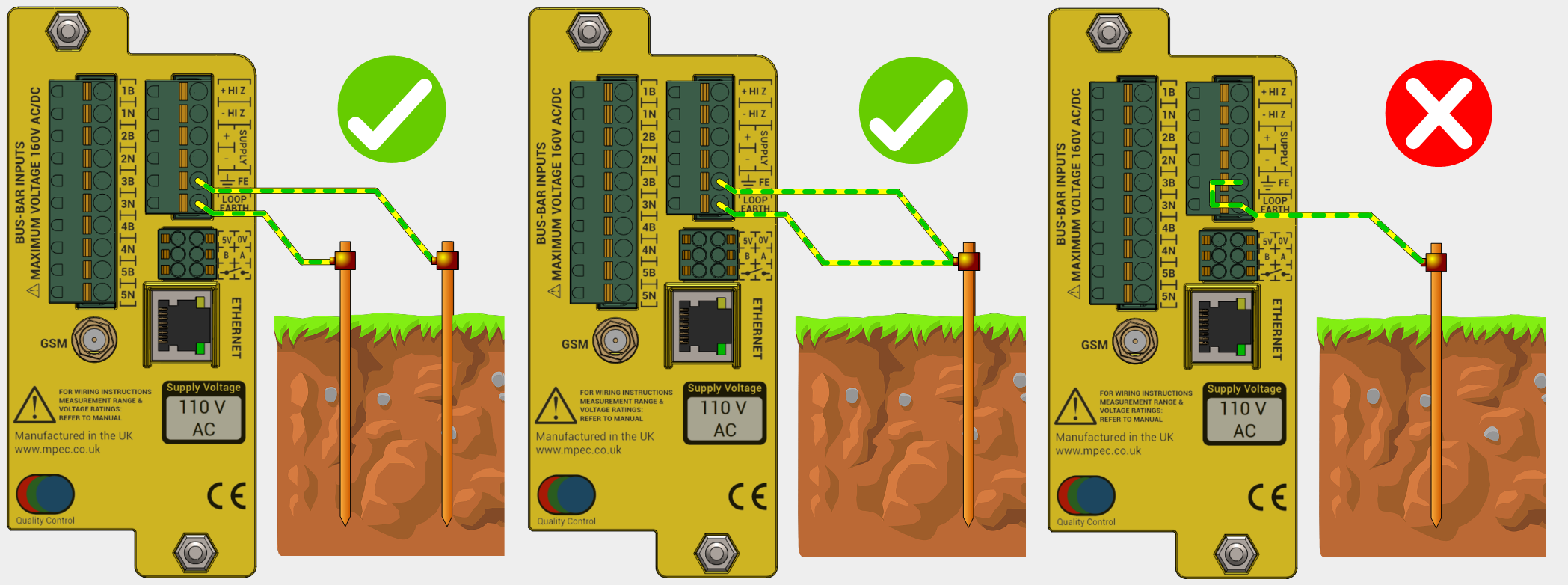
The Functional Earth and Loop Earth must be connected to suitable earthing points using separate wires.
- It is preferable to use independent earthing points for loop earth and functional earth connections.
- It is tolerable to use a common earthing point if provision of a secondary earthing point is prohibitive.
- It is not acceptable to simply strap Functional Earth to Loop Earth.
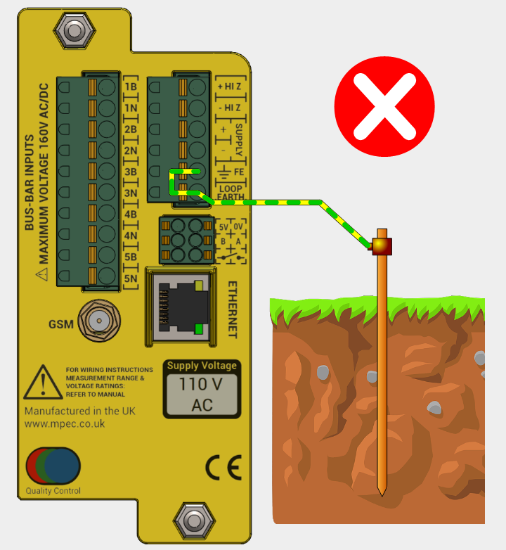
An ineffective Earth Loop circuit is unable to verify correct connection of the SA380-IT, hence insulation readings may be incorrect.
Wire the FE and LOOP EARTH in one of the two ways shown below:

Use green / yellow sleeved cable to differentiate earth connections from monitored circuit and power connections
Use appropriate cable markers, crimps & crimp tools for the earth bus-bar terminations.
Use appropriate tools to to affix the earth cables to bus-bar terminals.
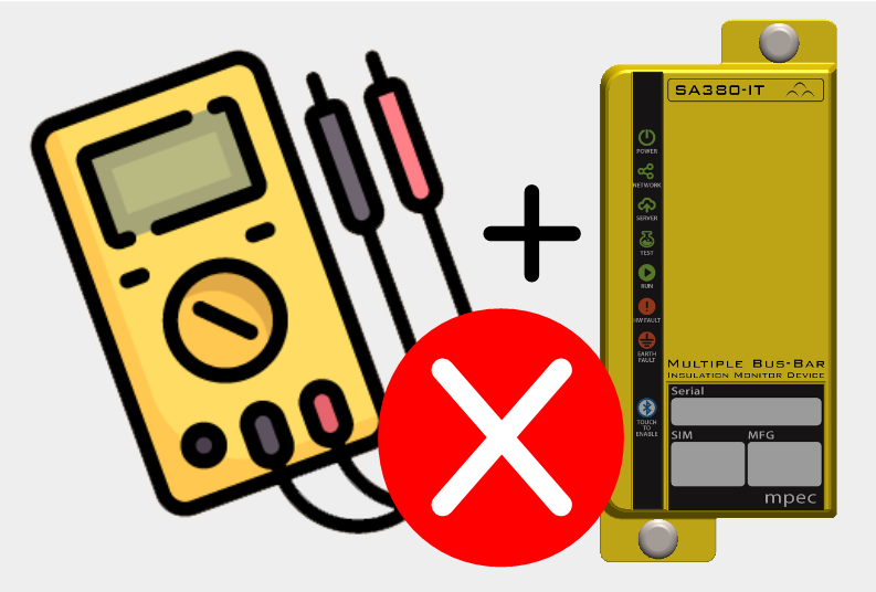
A manual continuity test between Functional Earth and Loop Earth connections after installation, but be aware that a standard digital multimeter may not obtain a true reading if stray voltages are present. If in doubt, use a earth-test device designed specifically for this purpose.
This measurement should therefore be considered a "sanity check" of the wiring, not the absolute resistance of the earth loop path.
- Earth loop readings <= 40 Ω between FE and Loop Earth connections is considered acceptable.
- Earth loop readings <= 500 Ω maybe considered tolerable by you organisation, but should be investigated,
3.9) Wiring of Input Circuits
| Parts | |
|---|---|
| 0.75 mm2 Shrouded Ferrule crimps |
|
| 0.75 mm2 stranded single core cable |
|
| Cable markers | No Image |
| Resistive cable modules |
|
| "Live End" circuit termination crimps | No Image |
| Optional circuit fuses | No Image |
| Tools | |
| Square Wire End Ferrule Crimper |
|
| Wire Stripper / Cutter |
|
| "Red" crimp tool |
|
| Additional Crimping / Fixing Tool(s) | No Image |

"Live end" crimp types and fuse-holder sizes vary, therefore no specific crimps or fuses are recommended.
If fuses are fitted to monitored circuits, these should be of smallest practical rating.
The maximum permissible voltage of montoried circuits is 160 V DC or 160 V AC RMS
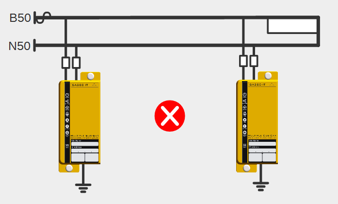
Only one insulation monitoring device may be used on a single interconnected circuit. Installation of additional monitoring devices will cause each device to "fight" the other, resulting in incorrect readings on both devices.
Ensure that any existing earth-leakage devices connected to monitored circuits have been disabled.
There are two means of connecting monitored circuits to the SA380-IT. Via resistive cables, or via the HiZ outputs:
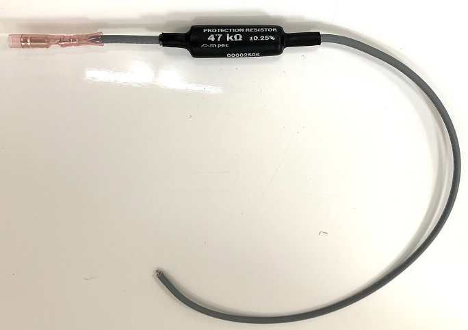
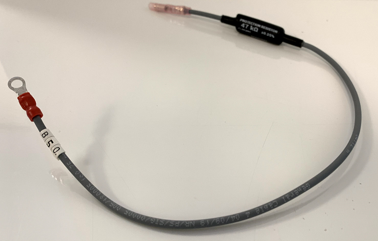
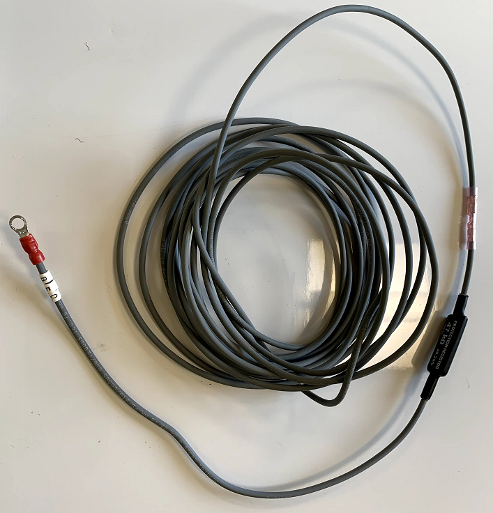
Resistive Cables
The SA380-IT device is typically supplied with resistive cables, or they can be purchased separately. The resistive cable features:
- a 47 kΩ resistor fitted in-line
- a 300 mm flying-lead to be terminated on the monitored circuit bus-bar.
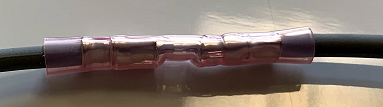
- an in-line through-crimp to allow extension of the resistive cable module with additional cable.
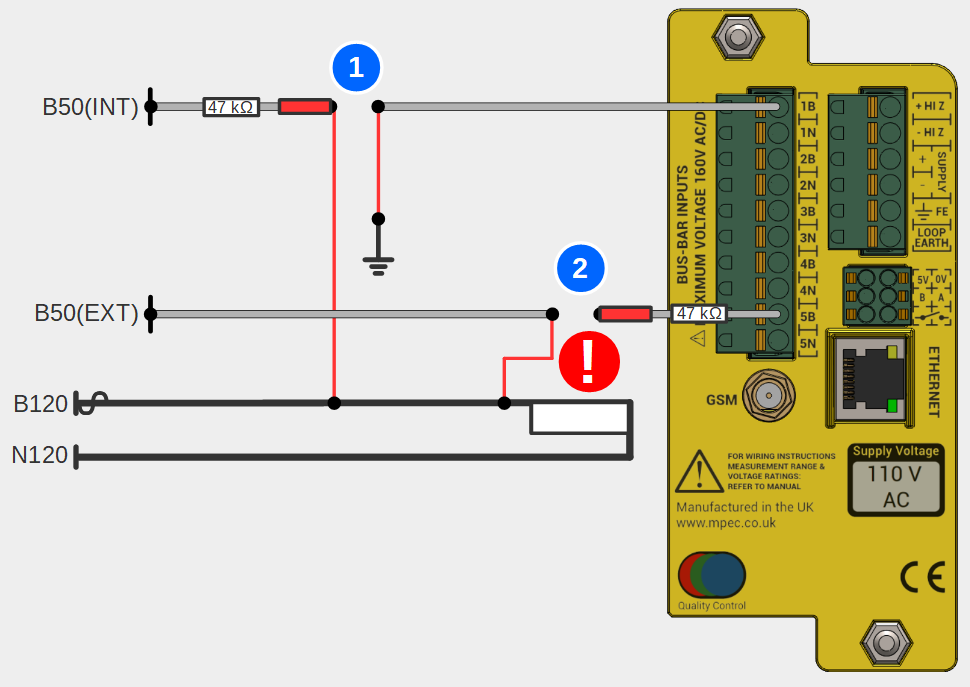
The purpose of the resistive cables are to limit current flow between monitored circuits in the event that any SA380-IT cabling inadvertently comes into contact with any other safety critical or high reliability circuits.
| No | Notes |
|---|---|
| 1 | Existing Earth Fault has compromised negative leg isolation |
| 2 | B50 shorts to B120 at rear of SA380-IT. |
| 3 | B120 shorts to N120 at rear of SA380-IT. |
| System remains safe due to protective resistance afforded by the connection cables | |
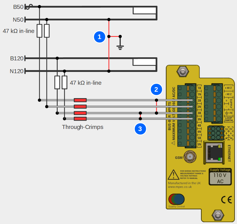
The purpose of the through crimp is to permit simple extension of cable runs from the SA380-IT to monitored circuits:
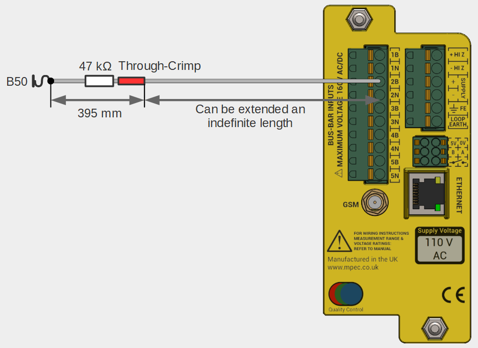
Failure of the through-crimp is mitigated by ensuring the in-line resistor is fitted facing the monitored circuit bus-bar connection.
| No. | Notes |
|---|---|
| 1 | Through Crimp Failure results in fault connections to other live circuits or earth. Supply remains protected by in-line resistor SA380-IT has internal >90 kΩ protective resistance |
| 2 | Through Crimp Failure results in fault connections to other live circuits or earth. Unsafe failure due to orientation of protective resistor. |
HiZ Outputs
It is common to perform monitored circuit functions on the same circuit that is used to power the SA380-IT device.
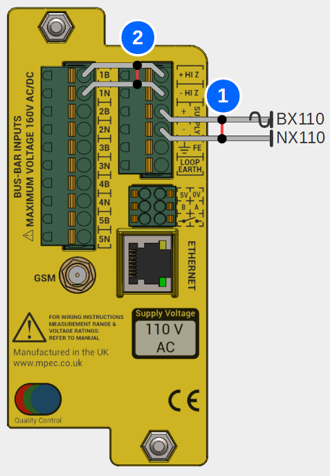
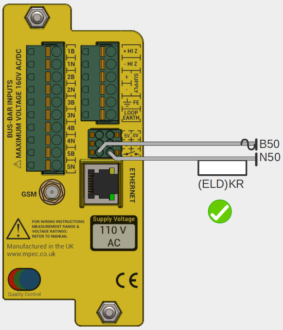
To simplify wiring it is possible to "jumper" across the power supply into "Channel 1" of the monitored circuits. This is achieved by the "HI Z" outputs.
The "HI Z" outputs present the power supply voltage as an output, albeit with a 47 kΩ resistor in each circuit leg. E.g.
BX HI Z is BX Supply with 47 kΩ in series.
NX HI Z is NX Supply with 47 kΩ in series.
This means that resistive cables are not required to jumper the HI Z outputs across to channel 1 as shown in the diagram below. The arrangement remains safe in the event of cable fault.
| No. | Notes |
|---|---|
| 1 | Short Circuit of the supply protected by mandatory provision of a supply circuit fuse. |
| 2 | Short Circuit of "HiZ" leads protected by internal 47 kΩ resistors |
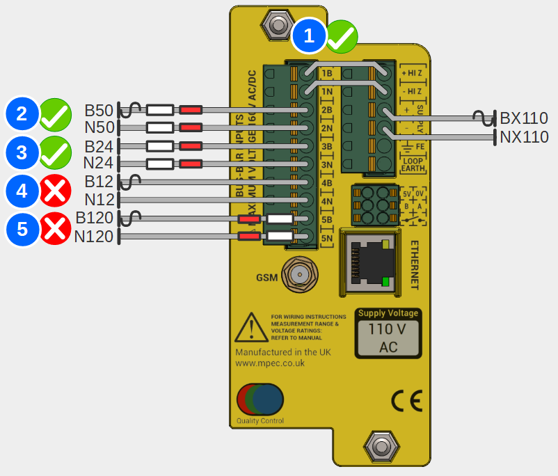
Please note the following important general wiring information:
| No. | Safe? |
|---|---|
| 1 | Yes |
| Connection of supply to "circuit 1" input using "Hi Z" supply output | |
| 2 | Yes |
| Correct fitment of resistive cables. Connection to circuit bus-bar is via an independent fuse. | |
| 3 | Yes |
Correct fitment of resistive cables No independent fuse is required for safe operation | |
| 4 | No |
| No resistive cable fitted. Circuit vulnerable to short-circuit faults. | |
| 5 | No |
| Incorrect fitment of resistive cable. Circuit vulnerable to through-crimp failure. | |
| No. | Safe? |
|---|---|
| 1 | No |
Do not "common" circuits. N50(E) and N50(I) isolation compromised | |
| 2 | No |
Ensure correct connector position alignment. N120 and B24 isolation compromised | |
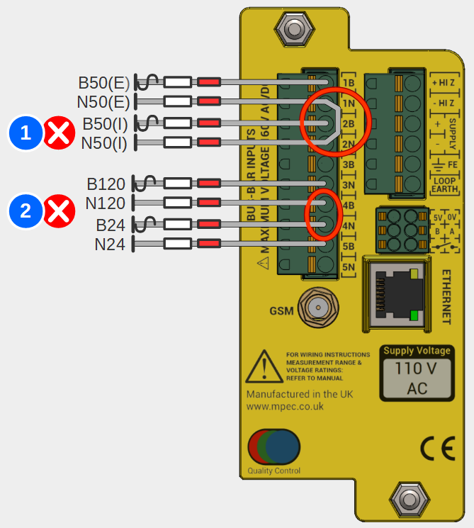
Not following this advice risks:
- Circumvention if the inter-isolation of monitored circuits.
- Short circuit of individual monitored circuits.
Electric shock.
Resistive Cables
Mark, strip and crimp the "live" end of the resistive cable module with an appropriate markers and crimps for the monitored circuits bus-bar connection.
It is permissible to shorten the "live" end of the resistive module cable if it aids installation.
- Starting at the SA380-IT, run correctly terminated and marked 0.75 mm2 single core cable from the SA380-IT rear connector to the monitored circuits connection point.
- Strip 12 mm of insulation from the end of the single core cable at the "connection point" end.
- Take a resistive cable module and splice the ordinary single core cable to the red PIDG through-crimp using the correct crimping tool.
- Check the crimped connection:
- No loose strands
- No copper exposed at either crimp end.
- Sufficient exposed wire held firm by the crimp
- An even profile.
- crimp is secure
- Preferred: Make terminations to bus-bars using a fused connection if appropriate. Fuses should be rated as low as possible. The SA380-IT should never draw >2 mA from the supply under any circumstance.
- Acceptable: If space is at a premium in existing installations, there is no safety risk in installing monitored circuit connections direct to bus-bars, circumventing a fused connection.
HiZ Outputs
- Prepare two correctly terminated and marked 0.75 mm2 single core cables 50 mm each in length
- Insert the 50 mm cables between input channel 1 and HiZ outputs.
3.10) GSM Connection
In railway settings the antenna must be fitted to the outside of the equipment enclosure (typically a location case or equipment room)
Affix the antenna head to the exterior of the equipment housing using the self-adhesive backing and back-nut.
This may require drilling a 12 mm hole.
- Affix the antenna tail cable using the SMA screw-fit connector to the rear of the logger.
- The SMA connector should be tightened by hand to avoid over-tightening
- Do not over tighten the connection. Optimum tightening torque is 1.0 Nm-1
Do not attempt to shorten the cable without appropriate specialist tools.
Do not force the antenna cable around tight bends.
See the commissioning section for information on verifying GSM signal strength.
| Parts | |
|---|---|
| GSM Antenna |
|
| Tools | |
| Drill + 12 mm Drill bit | No Image |
For non-panel mount scenarios, additional brackets may be required. These are not supplied with the SA380-IT.
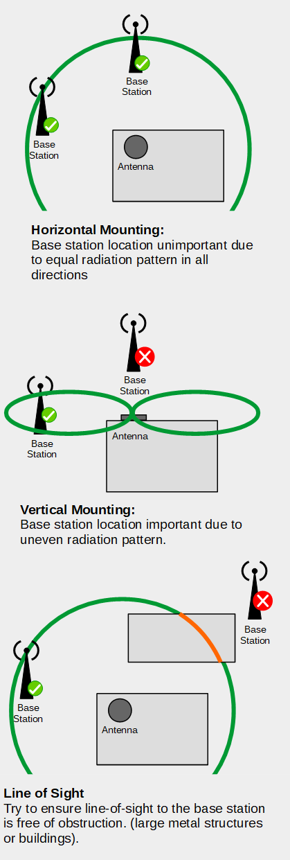
Antenna placement tips
The radiation pattern of the supplied antenna is a torus (doughnut) about the horizontal plane.
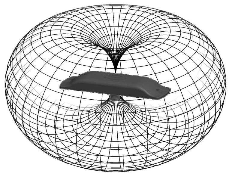
There is zero reception directly above or below the antenna, there is maximal and even reception around the horizontal plane.
The SA380-IT device is typically shipped with factory fitted SIM and GSM antenna.
Please liaise with MPEC to specify your desired SIM package
3.11) Ethernet Connection
| Parts | |
|---|---|
| Screened Ethernet Cable |
|
| Tools | |
| None | No Image |
The Ethernet port is sensitive to electrical surges:
Additional surge protection must be fitted if the port is to be used continuously for data transmission using:
- A dedicated Ethernet surge protection device, or
- Use of screened Ethernet cable
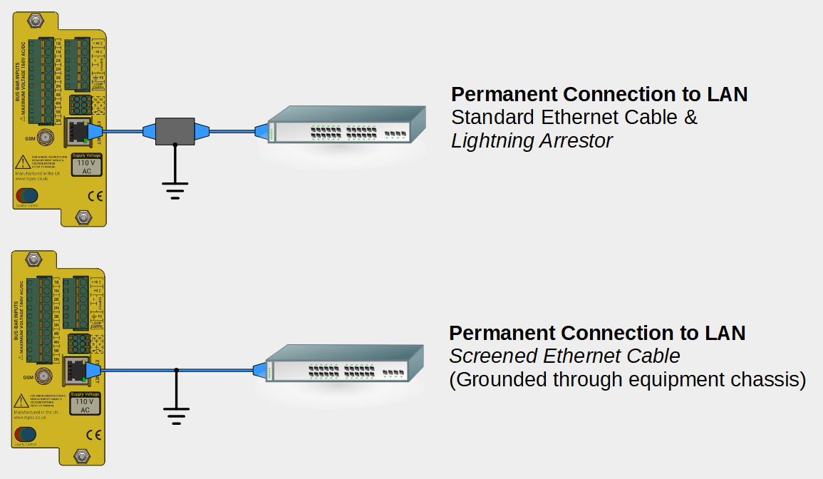
- Surge protection is not required for temporary configuration and diagnostics activities.
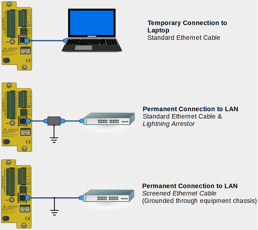
The Ethernet port accepts standard Ethernet cable via an RJ45 connector.
The Ethernet port can be used as a monitoring port with no additional surge protection required.
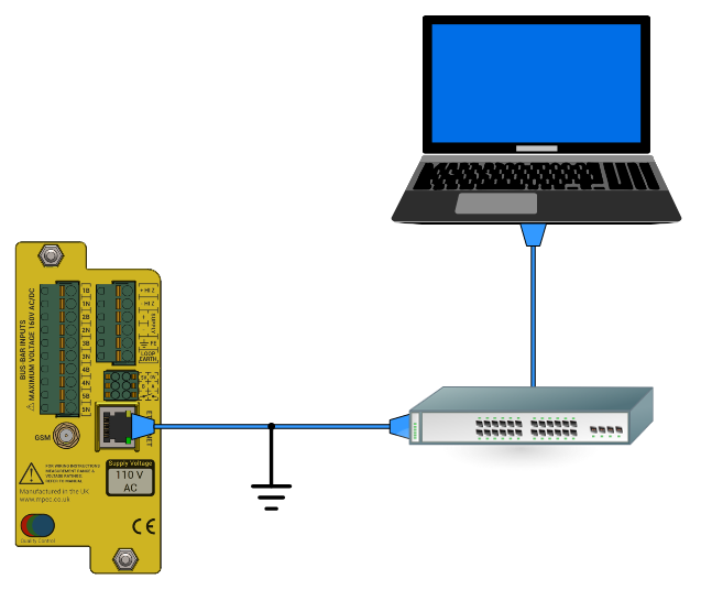
- If connecting direct to a computer, simply use an Ethernet patch cable to connect devices point to point.
- If using the Ethernet port as a permanent data connection then use either a screened Ethernet cable, or standard cable with surge arrestor to connect to a nearby modem or Ethernet switch/router.
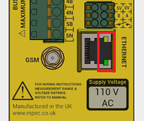
Successful connection can be verified by checking that the LAN port Link indication is lit solid, and the the activity indicator is blinking.
See the commissioning section for information on verifying Ethernet Connectivity.
See the operation section for detailed IP address settings information.
3.12) Wiring of Auxiliary Inputs
Crimp connections to external devices and circuits will vary, therefore no specific crimps are recommended.
Volt-Free-Contact
The maximum terminal voltage of the volt-free-contact output must not exceed 160 V RMS AC/DC.
Auxiliary Power
The maximum load of the auxiliary power supply output must not exceed 1 Watt.
RS485 Serial Data
RS485 functionality is not presently supported, but may be wired for future applications.
For wiring runs over 10 meters consider using screened cable as interference may be experienced.
For wiring runs over 30 meters, 100 Ω line-termination resistors should be fitted across the "A,B" terminations at both extremities of the data link.
| Parts | |
|---|---|
| 0.75 mm2 stranded single core cable |
|
| 0.75 mm2 Shrouded Ferrule crimps |
|
| Cable Markers | No Image |
| Circuit Termination Crimps | No Image |
| 0.5 mm2 Twisted Pair Cable |
|
| 0.5 mm2 Shrouded Ferrule Crimps |
|
| Tools | |
| Square Wire End Ferrule Crimper |
|
| Wire Stripper / Cutter |
|
| Additional Crimping / Fixing Tool(s) | No Image |
Volt-Free-Contact Output (VFC)
The VFC is used to give a local indication of hardware or earth fault.
The VFC acts as a simple switch, the polarity of connection is vital for the correct results.
The devices must be wired as the image below to ensure earth faults are detected.

The maximum voltage that can be applied across the VFC is 160 V RMS AC/DC
The VFC is to be wired into an alarm circuit, or VFC input of a data logging device as follows:
It is recommended to use correctly terminated 0.75 mm2 stranded single core cable for this connection.
Auxiliary Supply
A 5 V DC, 1 W regulated power supply is made available at the rear of the unit to power auxiliary sensors.
The output is short-circuit and overload protected.
Connect:
- 5 V terminal to the positive power terminal of the auxiliary equipment.
- 0 V terminal to the negative power terminal of the auxiliary equipment.
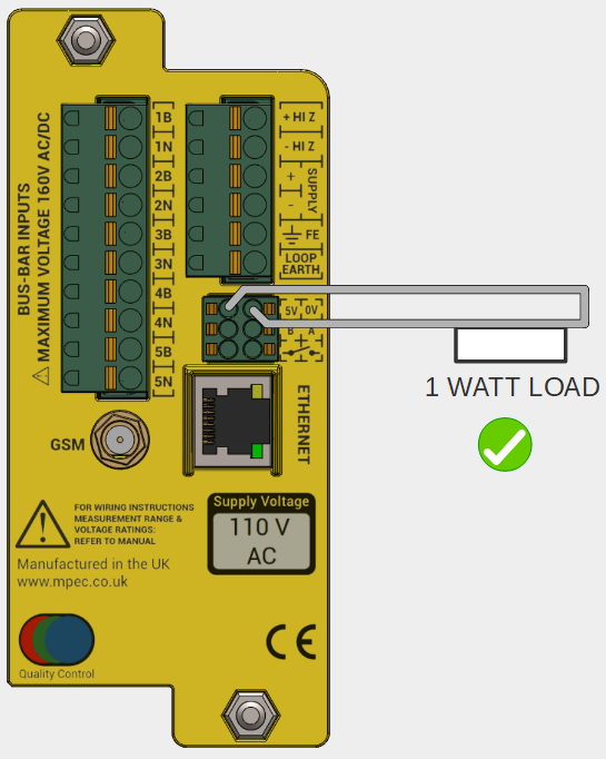
It is recommended to use correctly terminated 0.75 mm2 stranded single core cable for this connection.
RS485 Serial Data
The RS485 link is provided to allow data connection to auxiliary sensors and data logging equipment.
RS485 functionality is not presently supported, but may be wired for future applications.
It is recommended to use correctly terminated 0.50 mm2 twisted pair cable for this connection.
Wire "A" to "A" and "B" to "B" on all devices
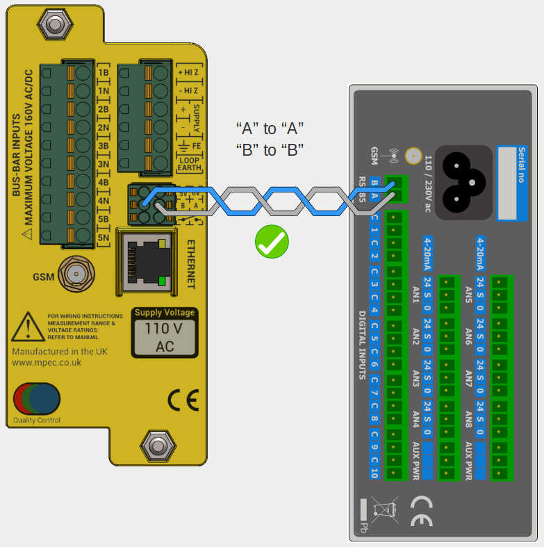
RS485 supports a multi-drop bus architecture, numerous devices can share the same RS485 bus.
4) Commissioning
4.1) Energise Device
- Visually inspect all wiring for sound installation.
- Measure voltages of the supply and monitored circuits and confirm they are within expected specification.
This will help confirm the the correct circuits are wired into the intended input channels, and will help verify correct set-up during subsequent commissioning steps.
- Connect the main supply fuse, applying power to the SA380-IT.
- Check SA380-IT front panel shows:
- Constant POWER indication
- Pulsating RUN indication
- A blinking Bluetooth indication
- Where fitted, connect fuses and/or links of monitored circuits.
4.2) Connect to Device
- Wireless configuration and diagnostics is facilitated by the "Mpec Connect" mobile app.
- Mpec Connect is presently compatible with iPhone and iPad (Running iOS 13+)
- Download and install the app by clicking on the icon below:

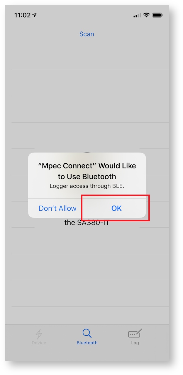
- Permit the App to use bluetooth
- The app will then attempt to pair with a nearby SA380-IT device
- The SA380-IT has bluetooth disabled by default. It can be enabled by:
- Restarting the device
- Activating the module using the touch-sensitive front-panel

- The bluetooth indicator will blink if the device is available for pairing.
- If the App discovers only one SA380-IT, pairing will take place automatically.
- If the App discovers multiple devices, the user will need to select the appropriate device to pair to.
- Devices are listed by their unique serial number.
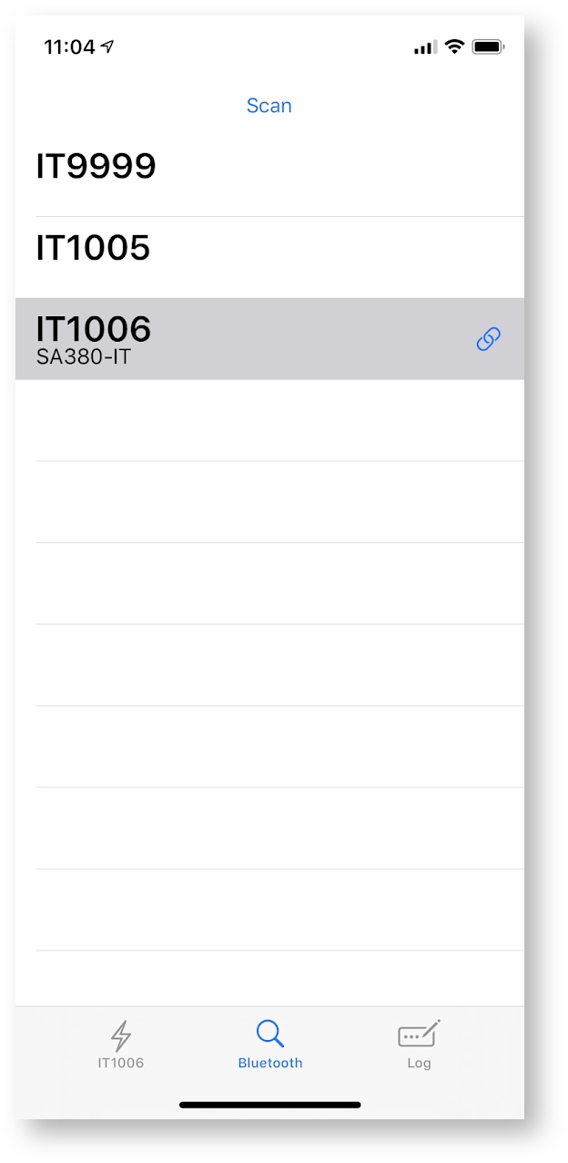
- The presently connected device is indicated by the
 indicator.
 - A successfully paired device will show a solid blue bluetooth indication on the front panel.
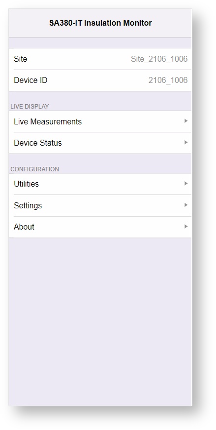
The SA380-IT home screen will automatically load in the
 device pane.
Bluetooth will switch off on the SA380-IT if the connection is left idle for 2 minutes. If this occurs, re-enable Bluetooth using the touch-sensitive front panel and reconnect to the device via the  view in the app.
You may need to set the time on the device if the SA380-IT is unable to locate a time-server using the GSM or Ethernet connections
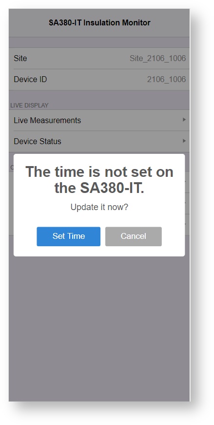
The SA380-IT will not perform any measurements if the time is not set.
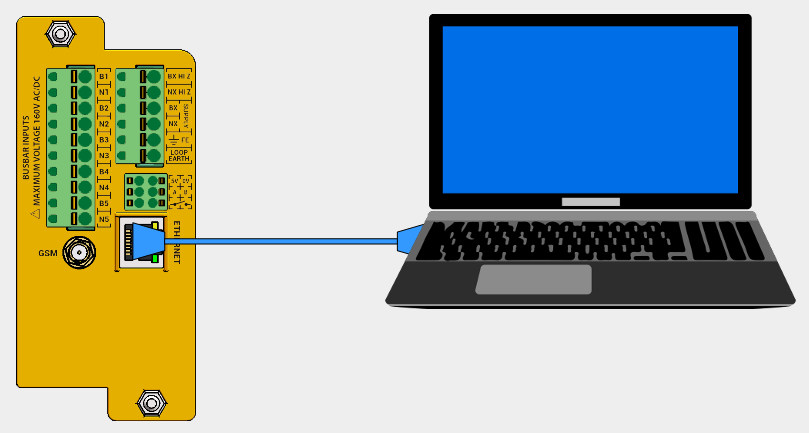
- Wired configuration and diagnostics can be performed on any Ethernet enabled device that runs a modern web browser.
- Connect Ethernet Cable.
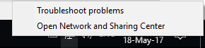
The following instruction apply to the "Windows 10" operating system, however the network settings will be the same regardless of operating system.
- Open Networks & Sharing Center:
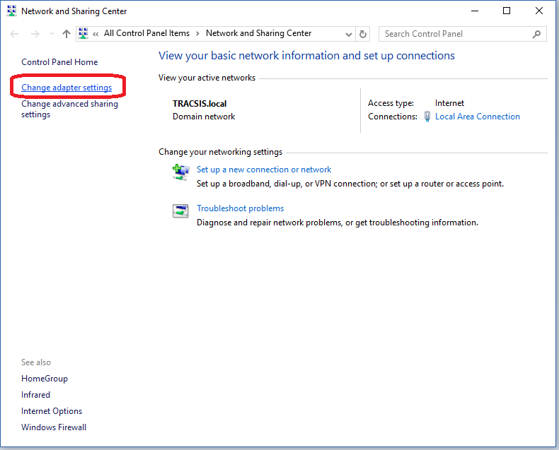
- Change Adapter Settings:
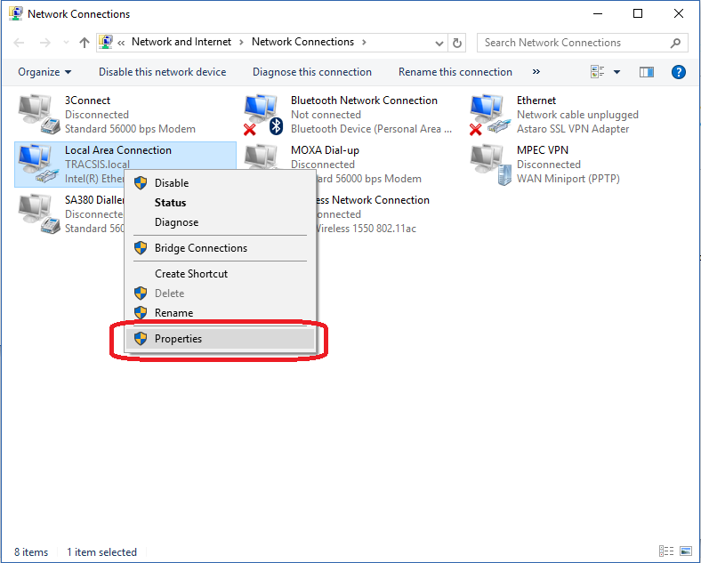
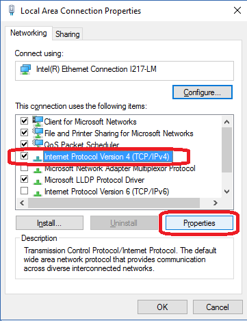
- On "Local Area Connection", right-click, select "Properties":
- Select "Internet Protocol Version 4 (TCP/IPv4)", then click "Properties":
- Use the following IP settings, then click OK:
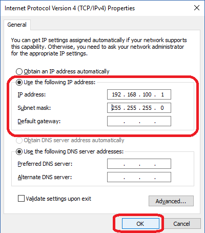
These settings assume that the SA380-IT resides on the 192.168.100.xxx sub-net. This is the default setting. If the IP address of your SA380-IT has been changed, You may need to change the IP settings above.
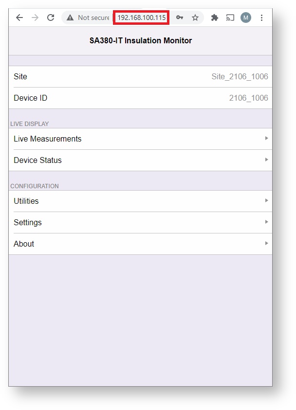
- Connect to the web-based configuration and diagnostics tool using any HTML 5 compatible web browser.
- Type the IP address of the SA380-IT into the address bar.
- The default IP address is 192.168.100.115.
You may need to set the time on the device if the SA380-IT is unable to locate a time-server using the GSM or Ethernet connections
The SA380-IT will not perform any measurements if the time is not set.
Any action that modifies the behaviour of the SA380-IT will require the operator to provide authentication details.
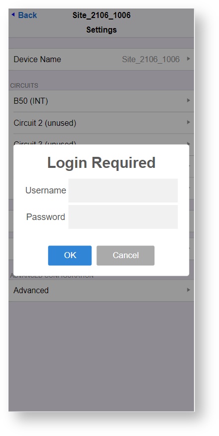
- Authentication details need only be provided once per connection session.
- Username and password details may be obtained from:
- Mpec technology by emailing: support@mpec.co.uk
- Project support staff from within your organisation.
4.3) Check for Latest Firmware
Mpec always recommend that you check for the latest firmware at commissioning time.
New firmware will always offer enhanced performance, bug-fixes and security patches versus older firmware.
UK - Network Rail RADAR users
The following applies if you are using your SA380-IT
- In the UK, and work for or on behalf of Network Rail.
- Your device is configured for deployment on the Network Rail RADAR (Formerly Intelligent Infrastructure) system.
In this instance your SA380-IT will attempt to perform an automatic firmware update from RADAR servers using the FTP protocol.
This update can take up to 30 minutes, during which time, you will not be able to configure and therefore commission the SA380-IT.
If an FTP based upgrade attempt is underway, you will be able to determine so using the Device Status page:
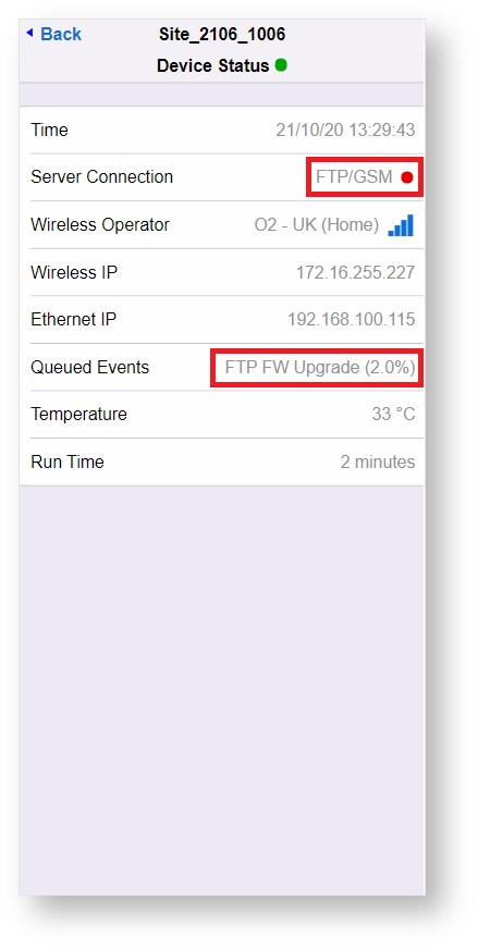
FTP firmware upgrade can be overridden by performing a local firmware upgrade to the latest approved firmware by following the steps outlined below.
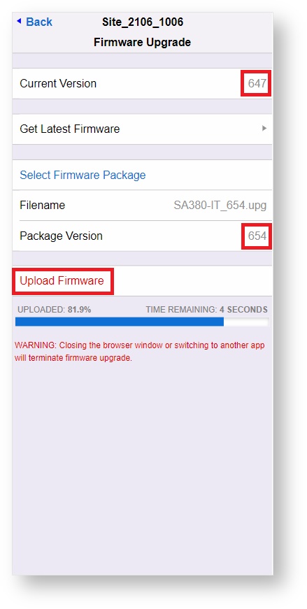
Navigate to Utilities→Firmware Upgrade
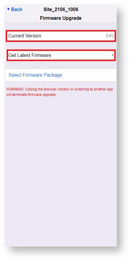
Make a mental note of your current firmware version
Click the Get Latest Firmware link to open a page in a new window that displays the latest recommended firmware packages for the SA380-IT

- Centrix users should use Centrix Approved firmware
- Network Rail RADAR users should use NR II Approved firmware
If the latest approved firmware is in advance of your installed version, then the update should be downloaded and installed.
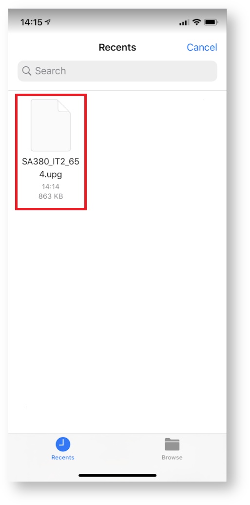
To commence firmware upload, return the Firmware Upgrade screen and choose Select Firmware Package.
To pick firmware files on iPhone/iPad

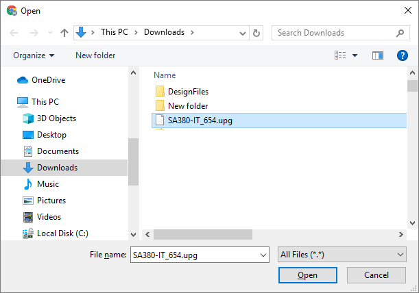
To pick firmware files in a Web Browser
Once satisfied with the current version and package version, select Upload Firmware to perform the upgrade.
The device will restart once upgrade is complete.
4.4) Check Earth Loop Reading
Navigate to Live Measurements:
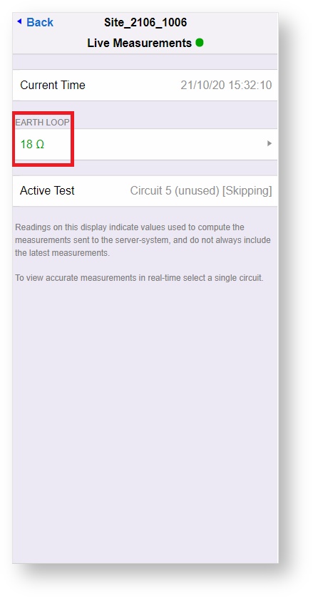
Check that the EARTH LOOP reading is in line with that measured during installation.
The SA380-IT will take resistance-to-earth readings of monitored circuits with an earth-loop resistance as high as 1,000 Ω given the default configuration of the device, however at commissioning:
- Earth loop readings <= 40 Ω between FE and Loop Earth connections is considered acceptable.
- Earth loop readings <= 500 Ω maybe considered tolerable by you organisation, but should be investigated,
4.5) Configure Monitored Circuits
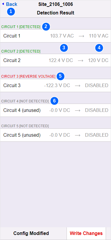
The Auto-detect feature of the SA380-IT is designed to speed up commissioning of the SA380-IT by detecting the nominal circuit voltage and type (AC or DC) of connected circuits.
- To run auto-detect. Navigate to Settings and select Auto-Detect.
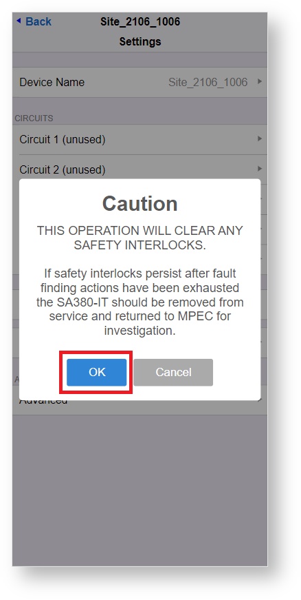
- You will have no safety interlocks engaged on a new device with an operable earth-loop.
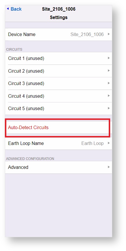
The SA380-IT will automatically detect which circuits are in use and assign these circuits a "common" railway nominal voltage:
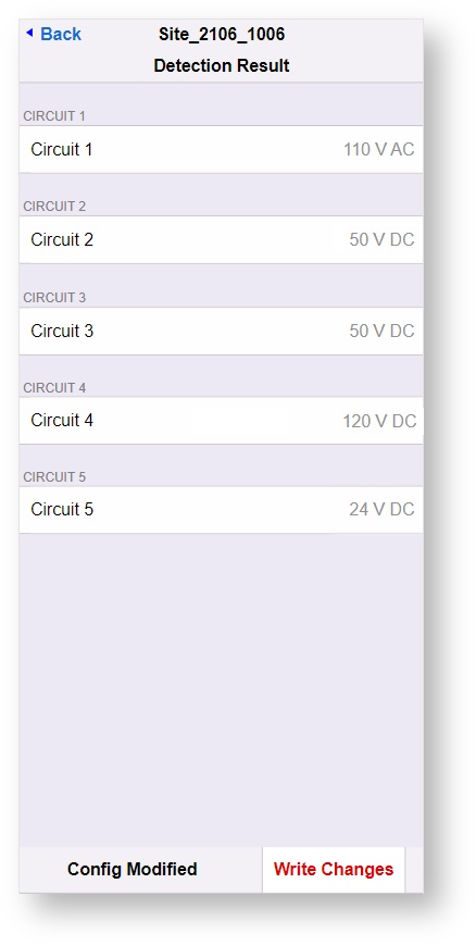
Once completed, remember to Write Changes, to save the configuration.

Although autodetect will be enough to commission a SA380-IT in most scenarios, you may wish to change some of the circuit settings in order to:
- Make the Circuit simple to identify, both on-site, and in any Enterprise Asset Management system.
- Adjust the nominal circuit voltage if the autoset levels are inappropriate.
Individual circuit settings are accessible from the Settings page:
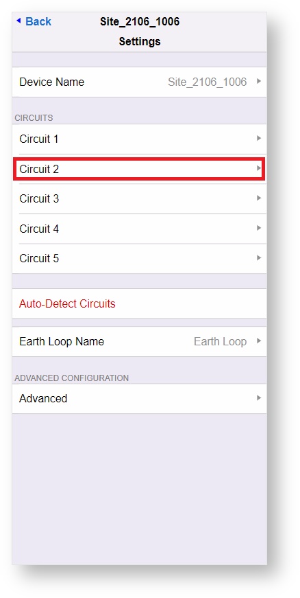
Rename circuits as appropriate:
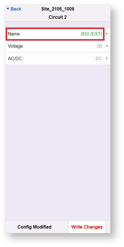
You may wish to change the nominal voltage of the circuit.
Nominal voltage is used to drive important safety features of the SA380-IT
It is important that this is set correctly.
Nominal voltage may be set incorrectly due to:
- The voltage being uncommon, hence autodetect failed to correctly identify the target voltage.
- The circuit voltage is high. This can commonly be found in railway circuits with long cable runs and heavy loads.
Enter a new nominal voltage that aligns with typical measured voltage of the circuit in question:
Remember to save any changes:
Navigate to Live Measurements:
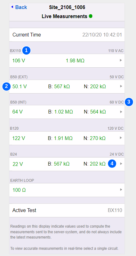
Check the following:
| 1 | Circuit is named correctly |
| 2 | SA380-IT measured voltage matches manual measured voltage |
| 3 | Nominal circuit voltage correct |
| 4 | SA380-IT resistance-to-earth readings match manual readings taken prior to installation. |
Refer to the troubleshooting guide in the event of any issue.
4.6) Check for Server Connection
The SA380-IT should be preconfigured to connect to your Enterprise Asset Management System. (EAMS)
If connectivity settings need to be changed, please refer to the operation section of this guide.
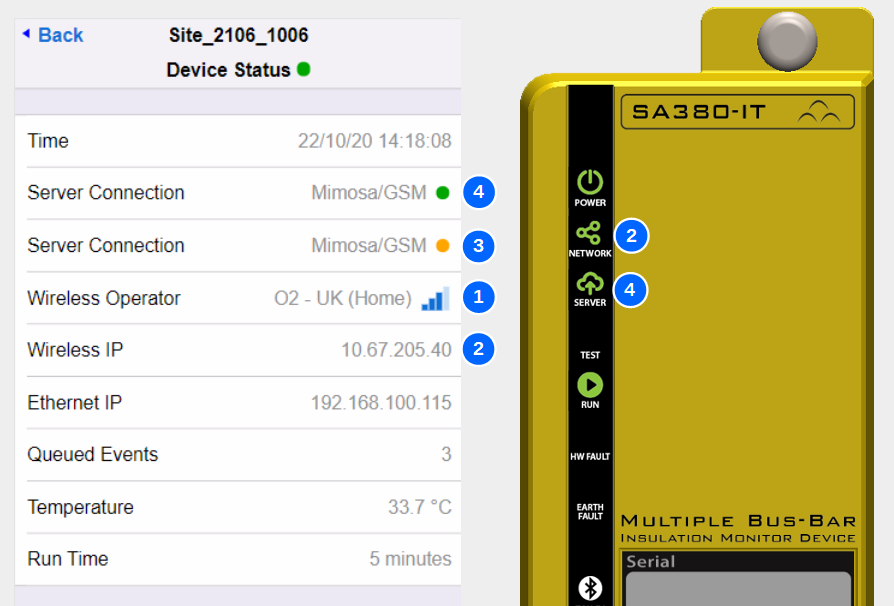
Use the images and table below to assess if server GSM connection has been established.
Refer to the troubleshooting guide in the event of any issue.
| 1 | SIM Registered with Operator |
| Requires active SIM and good signal strength | |
| 2 | Data Session Active |
| Requires SIM on correct tariff and correct APN settings | |
| 3 | Server Connection Handshaking |
| Requires active EAMS and correct server and protocol settings | |
| 4 | Server Connection Established |
| Requires that the SA380-IT is "deployed" on the EAMS |
The SA380-IT should be preconfigured to connect to your Enterprise Asset Management System. (EAMS)
If connectivity settings need to be changed, please refer to the operation section of this guide.
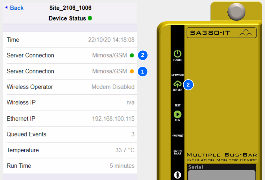
Use the images and table below to assess if server Ethernet connection has been established.
Successful Ethernet connection is highly dependent on correct IP settings on the the SA380-IT and all network infrastructure.
Refer to the troubleshooting guide in the event of any issue.
| 1 | Server Connection Handshaking |
| Requires active EAMS and correctly configured network, plus correct server, protocol & IP settings | |
| 2 | Server Connection Established |
| Requires that the SA380-IT is "deployed" on the EAMS |
4.7) Troubleshooting
5) Detailed Operation
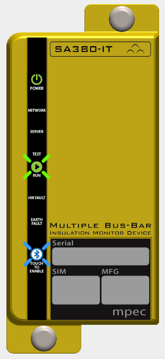
5.1) Front Panel Indications
| 1 | POWER | |
|---|---|---|
| On | Off | Flash |
| Device has power | Device un-powered or faulty | Device Faulty |
| 2 | NETWORK | |
| On | Off | Flash |
| Connected to GSM Network | Not connected to GSM network, or connected over Ethernet | Device Fault |
| 3 | SERVER | |
| On | Off | Flash |
| Connected to EAM server | No connection to EAM server, or device in "fallback" | Device Fault |
| 4 | TEST | |
| On | Off | Flash |
| Self-test underway | Self-test inactive | Device Fault |
| 5 | RUN | |
| On | Off | Flash |
| Software crash - device fault | Software crash - device fault | Pulsates - Software running |
| 6 | HW FAULT | |
| On | Off | Flash |
| Device hardware fault, monitored circuit voltage or earth loop irregularity | Device OK | Device fault |
| 7 | EARTH FAULT | |
| On | Off | Flash |
| One or more monitored circuits has a reportable earth fault. | Monitored Circuits OK. | Device fault |
| 8 | BLUETOOTH | |
| On | Off | Flash |
| Bluetooth active and paired to mobile device. | Bluetooth radio inactive | Bluetooth active and awaiting pairing |
5.2) Connecting to the SA380-IT
- Wireless configuration and diagnostics is facilitated by the "Mpec Connect" mobile app.
- Mpec Connect is presently compatible with iPhone and iPad (Running iOS 13+)
- Download and install the app by clicking on the icon below:
- Permit the App to use bluetooth
- The app will then attempt to pair with a nearby SA380-IT device
- The SA380-IT has bluetooth disabled by default. It can be enabled by:
- Restarting the device
- Activating the module using the touch-sensitive front-panel
- The bluetooth indicator will blink if the device is available for pairing.
- If the App discovers only one SA380-IT, pairing will take place automatically.
- If the App discovers multiple devices, the user will need to select the appropriate device to pair to.
- Devices are listed by their unique serial number.
- The presently connected device is indicated by the indicator.
- A successfully paired device will show a solid blue bluetooth indication on the front panel.
The SA380-IT home screen will automatically load in the
device pane.
Bluetooth will switch off on the SA380-IT if the connection is left idle for 2 minutes. If this occurs, re-enable Bluetooth using the touch-sensitive front panel and reconnect to the device via the view in the app.
You may need to set the time on the device if the SA380-IT is unable to locate a time-server using the GSM or Ethernet connections
The SA380-IT will not perform any measurements if the time is not set.
- Wired configuration and diagnostics can be performed on any Ethernet enabled device that runs a modern web browser.
- Connect Ethernet Cable.
The following instruction apply to the "Windows 10" operating system, however the network settings will be the same regardless of operating system.
- Open Networks & Sharing Center:
- Change Adapter Settings:
- On "Local Area Connection", right-click, select "Properties":
- Select "Internet Protocol Version 4 (TCP/IPv4)", then click "Properties":
- Use the following IP settings, then click OK:
These settings assume that the SA380-IT resides on the 192.168.100.xxx sub-net. This is the default setting. If the IP address of your SA380-IT has been changed, You may need to change the IP settings above.
- Connect to the web-based configuration and diagnostics tool using any HTML 5 compatible web browser.
- Type the IP address of the SA380-IT into the address bar.
- The default IP address is 192.168.100.115.
You may need to set the time on the device if the SA380-IT is unable to locate a time-server using the GSM or Ethernet connections
The SA380-IT will not perform any measurements if the time is not set.
Configuration and diagnostics can be performed remotely via Ethernet or GSM when the SA380-IT is configured with a fixed, routable IP address.
This can be via a fixed LAN configuration:
or via a GSM connection that offers a fixed IP address:
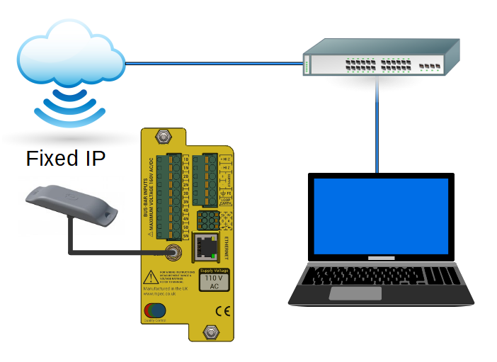
Remote Ethernet and GSM connection requires a correctly configured LAN and/or SIM package. The set-up and provision of which is beyond the scope of this user guide.
The SA380-IT will offer 2 different IP addresses:
| 1 | IP address of the wireless GSM interface |
| 2 | IP address of the wired Ethernet interface |
Connect to the web-based configuration and diagnostics tool using any HTML5 compatible web browser.
Type the IP address (as referenced above) into the address bar to access the SA380-IT.
You may need to set the time on the device if the SA380-IT is unable to locate a time-server using the GSM or Ethernet connections
The SA380-IT will not perform any measurements if the time is not set.
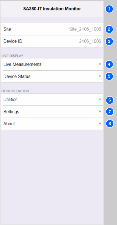
5.3) Main Menu
| No. | Name | Description |
|---|---|---|
| 1 | Title | The Main Menu title is simply "SA380-IT Insulation Monitor" |
| 2 | Site | The name of the installation. Can be changed in "Settings" |
| 3 | Device ID | The unique ID of the device. Cannot be changed. |
| 4 | Measurement Data | Click here to access live measurement readings of monitored circuits. |
| 5 | Device Status | Click here to access live connectivity and device health information. |
| 6 | Utilities | Click here to access engineering functions such as device and communications reset, time update and firmware upgrade. |
| 7 | Settings | Click here to access all device settings. |
| 8 | About | Click here to view hardware and software build information. |
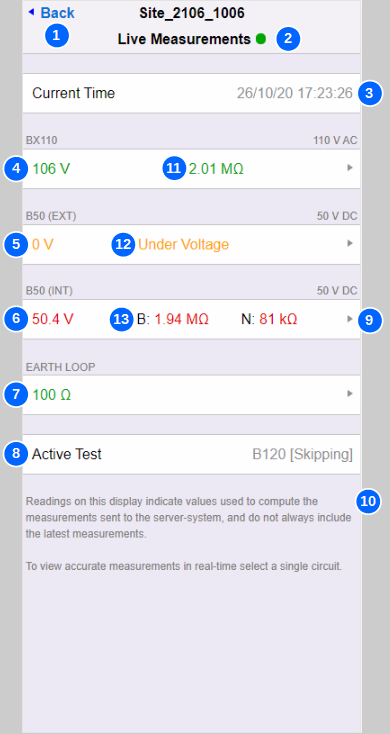
5.4) Live Measurements
| No. | Name | Description |
|---|---|---|
| 1 | Back | Return to main menu |
| 2 | Connection Status | A green dot indicates a live connection to the device. A yellow dot denotes that the device has become unresponsive, but may recover. A red dot denotes that the connection has been lost. |
| 3 | Time | The current time set on the device. |
| 4 | AC Monitored Circuit | AC monitored circuits show circuit voltage and equivalent resistance to earth (RL). |
| 5 | Locked Monitored Circuit | This circuit is suffering from a lock-out condition hence no resistance to earth reading has been taken. Only voltage |
| 6 | DC Monitored Circuit | DC monitored circuits show circuit voltage and equivalent resistance to earth of each circuit leg (RB and RN). |
| 7 | Earth Loop Resistance | The resistance between FE and Loop Earth terminals. |
| 8 | Current Test | Displays the test currently being performed by the device at the moment the page refreshed. |
| 9 | Technicians Mode | Clicking on the white region of a monitored circuit or earth loop display will cause the device to enter technicians mode for that particular circuit. |
| 10 | Disclaimer | The readings displayed on this screen show the measurements used to compute values that should be sent to the server-system. Measurements are scheduled to provide a balance between catching fast transient to earth faults, but also slower high-resistance / high-capacitance measurements for multiple circuits. To observe accurate and responsive measurement of a single circuit, use technicians mode. |
| 11 | Green Text | ..is used to denote monitored circuits where resistance to earth is above the defined alert thresholds. ..is used to denote that earth loop resistance is below the defined alert threshold. |
| 12 | Orange Text | ..is used to denote monitored circuits suffering from a recoverable lock-out condition |
| 13 | Red Text | ..is used to denote monitored circuits where resistance to earth is below the defined alert thresholds. ..is used to denote that earth loop resistance is above the defined alert threshold. ..is used to denote monitored circuits suffering from an unrecoverable lock-out condition |
| Info | Missing Circuits | Only monitored circuits configured for measurement are displayed. |
For a full description of device lock-out behaviour, and the status and meaning of resistance-to-earth readings, see the Principals of operation section of this user guide.
5.5) Technicians Mode
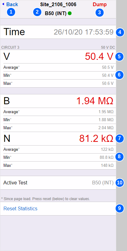
| No. | Name | Description |
|---|---|---|
| 1 | Back | Navigates back to the live measurements screen and terminates technicians mode. |
| 2 | Circuit Name & Connection Status | The name of the monitored circuit. A green dot indicates a live connection to the device. A yellow dot denotes that the device has become unresponsive, but may recover. A red dot denotes that the connection has been lost. |
| 3 | Dump | Displays a detailed diagnostic data dump (for manufacturers use). |
| 4 | Time | The current time. |
| 5 | Voltage | The monitored circuits present voltage. Not displayed if earth loop resistance has been selected. |
| 6 | Avg / Min / Max | Average, minimum and maximum voltage readings since technicians mode was entered or statistics reset. |
| 7 | Resistance | AC monitored circuits show equivalent resistance to earth (RL). DC monitored circuits show equivalent resistance to earth of each circuit leg (RB and RN). The Earth Loop circuit shows the present resistance between FE and Loop Earth terminals. |
| 8 | Avg / Min / Max | Average, minimum and maximum resistance readings since technicians mode was entered or statistics reset. |
| 9 | Reset Statistics | Reset all the average, minimum and maximum statistics for the page. |
| 10 | Technicians Mode | Whilst in technicians mode, only the selected circuit is measured. This improves response time for the circuit of interest to aid faulting activities. No other monitored circuit is measured, earth loop resistance is not measured (unless selected), device integrity checks are not performed. The user should manually exit technicians mode when it is no longer required such that other measurements recommence. If the user should forget to leave technicians mode, normal mode will automatically resume after a period of 4 hours. |
| info | Green Text | ..is used to denote monitored circuits where resistance to earth is above the defined alert thresholds. ..is used to denote that earth loop resistance is below the defined alert threshold. |
| info | Orange Text | .is used to denote monitored circuits suffering from a recoverable lock-out condition |
| info | Red Text | ..is used to denote monitored circuits where resistance to earth is below the defined alert thresholds. ..is used to denote that earth loop resistance is above the defined alert threshold. ..is used to denote monitored circuits suffering from an unrecoverable lock-out condition |
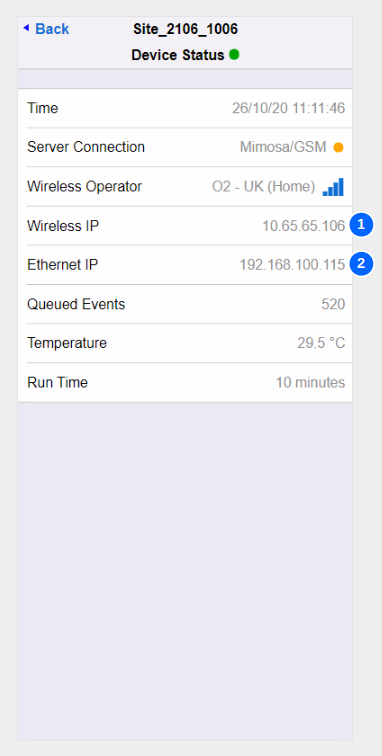
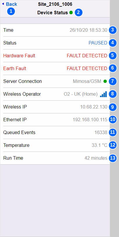
5.6) Device Status
| No. | Name | Description | ||||||||||||||||||
|---|---|---|---|---|---|---|---|---|---|---|---|---|---|---|---|---|---|---|---|---|
| 1 | Back | Navigates back to the main menu | ||||||||||||||||||
| 2 | Connection Status | A green dot indicates a live connection to the device. A yellow dot denotes that the device has become unresponsive, but may recover. A red dot denotes that the connection has been lost. | ||||||||||||||||||
| 3 | Time | The current time. | ||||||||||||||||||
| 4 | Device Status | Shows if the device is presently paused or in technicians mode | ||||||||||||||||||
| 5 | Hardware Fault | Will be present if the HW FAULT indication is lit. See device syslog for detailed diagnostics. | ||||||||||||||||||
| 6 | Earth Fault | Will be present if the EARTH FAULT indication is lit. See live measurements for detailed diagnostics. | ||||||||||||||||||
| 7 | Server Connection | The text Indicates the present server protocol followed by the server connection method: Protocol
Bearer
Connection Status
| ||||||||||||||||||
| 8 | Wireless Operator | Displays the connection state of the modem: Blank: Modem not configured. Waiting for Modem: The SA380-IT is waiting for the modem to power-up. Searching: The modem is searching for an operator. Operator Name: When registered with an operator, the operator name, and GSM signal strength is displayed. Signal Strength:
| ||||||||||||||||||
| 9 | Wireless IP | The IP address obtained by the modem for the GPRS data session: Blank: GSM modem off or not registered with a carrier. Valid IP Address: GPRS session successfully established. | ||||||||||||||||||
| 10 | Ethernet IP | The SA380-IT does not support DHCP, and can therefore not request an IP from another device. The Ethernet IP address is "static" and assigned by the user through configuration. It is the configured IP address that is displayed here. | ||||||||||||||||||
| 11 | Queued Events | How many data events are awaiting transmission to the server. | ||||||||||||||||||
| 12 | Temperature | Internal temperature of the SA380-IT. | ||||||||||||||||||
| 13 | Run Time | How long the SA380-IT has continuously operating since last reboot. |
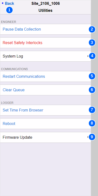
5.7) Utilities
| No. | Name | Description |
|---|---|---|
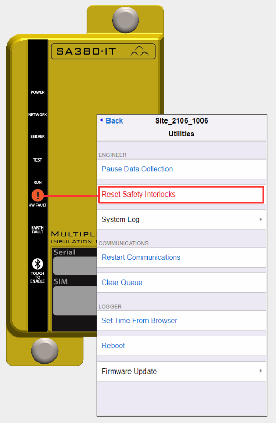
| 1 | Back | Navigates back to the main menu. |
| 2 | Pause Data Collection / Resume Data Collection | This toggles the SA380-IT between paused mode and normal mode. The SA380-IT will not attempt any measurement during suspended mode, nor connect any monitored circuit to the measurement circuitry or earth. The user should manually exit suspended mode when it is no longer required such that measurements recommence. If the user should forget to terminate suspended mode mode, normal mode will automatically resume after a period of 4 hours. |
| 3 | Reset Safety Interlocks | This will immediately clear any safety interlocks that are presently restricting measurement. Ensure that you have exhausted all fault finding tasks prior to manually resetting any device interlock. |
| 4 | System Log | Opens the System log page to retrieve detailed diagnostic data. |
| 5 | Restart Communications | This will drop any existing communication link and attempt to build up the link again from scratch. When using the MIMOSA protocol this will reset any back-off period. When using the GSM modem, the modem will restart. |
| 6 | Clear Queue | This will erase all pending messages waiting to be sent to the server. The data will be permanently lost. |
| 7 | Set Time From Browser | The SA380-IT requires the time to be set before measurement can commence. This is normally done through connection to time server. In the event that a time server is unavailable the time can manually be set using this feature. |
| 8 | Reboot | Performs a software restart of the device. |
| 9 | Firmware Update | Opens the Firmware update screen. |
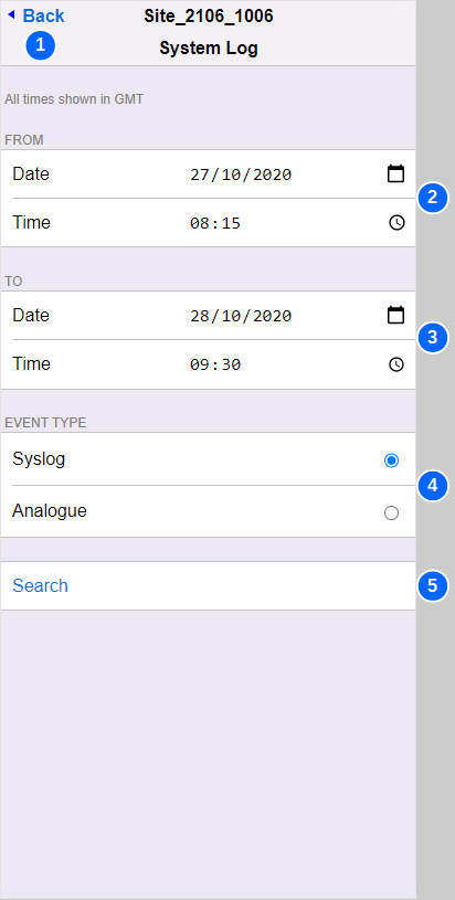
5.8) Syslog
| No. | Name | Description |
|---|---|---|
| 1 | Back | Navigates back to the main menu. |
| 2 | Start Date / Time | The time and date from which you wish to interrogate the system logs. The default setting on one hour in past. |
| 3 | End Date / Time | The time and date at which you wish to finish interrogating the system logs. The default setting on 24 hours hence. |
| 4 | System Log Filter | Filters the System Log to show either "Analogue Data" (Measurements) or "Syslog" (event log) events. |
| 5 | Search | Click ./ Tap to begin search. Be aware this can take some time, especially on slow 2G GSM connections. |
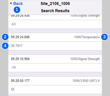
| No. | Name | Description |
|---|---|---|
| 1 | Back | Navigates back to the System Log menu |
| 2 | Date / Time stamp | The time and date of the system log entry |
| 3 | Channel | The channel to which this measurement belongs. |
| 4 | Value | The value of the measurement. |
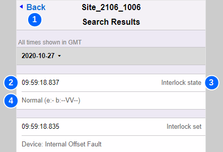
| No. | Name | Description |
|---|---|---|
| 1 | Back | Navigates back to the System Log menu |
| 2 | Date / Time stamp | The time and date of the system log entry |
| 3 | Entry Type | The type of System Log entry (See table below) |
| 4 | Additional Info | Many syslog entries contain additional informative text that describe system behaviour. (See table below) |
A brief description of System Log entries is shown below. If further detailed technical advice is sought. Please contact Mpec for support.
| Syslog Entry | Description |
|---|---|
| Interlock state [reason] [circuits] | A new interlock has fired.... [reason] explains the reason for the interlock system log entry. See the principles of operation section for a definitive list of all interlock types. [circuits] lists the affected circuits in the format e:- b:----- e: represents the Earth Loop Health b: represents the health of the internal test circuit and five monitored circuit inputs. This is indexed with the Internal test circuit first, followed by the five monitored circuits. '-' represents a healthy circuit 'V' represents a voltage fault on the affected circuit 'E' represents an earth fault on the affected circuit so, for instance Interlock State Overvoltage e:- b:--VV-- means
|
| Centrix connected | Confirmed as connected to a Centrix server. |
| Centrix disconnected | Confirmed as disconnected from a Centrix server. |
| Config changed by remote user | Configuration changed via Bluetooth, or via web-pages. |
| Config changed by MIMOSA | Configuration changed by the Network Rail II server. |
| Interlocks cleared | User issued "reset interlocks" command |
| Logger active | SA380-IT has booted and is now running. |
| Mimosa client ended | Device will now send MIMOSA messages |
| Mimosa server ended | Device no longer listening for MIMOSA messages |
| FTP handler | Device is attempting firmware upgrade |
| FTP download error | An error has occurred during FTP firmware upgrade |
| M My IP | Records the IP address used by the device |
| M My IP changed! | Records changes to the IP address |
| M Rx HTTP error | Logs HTTP error response codes from the server. |
| M Rx No response from core sys | The Network Rail II system is unreachable due to lack of connectivity or the server is not running. |
| M Rx HTTP 200 - OK | The last message sent to the server was accepted. |
| M Tx aborted | Message transmission aborted due to timeout - unable to connect to the server, or transmission took too long. |
| M Tx Fallback for | There will be a fallback "delay" before attempting to send another message. |
| Queue Information | Invalid queue update attempted (RailDAQ mode). |
| Modem command | Displayed the last command sent to the device modem. |
| Modem command failed | The modem failed to respond to the last modem command. |
| Modem power off | The modem has been turned off. |
| Modem power on | The modem has been turned on. |
| Restarting system | The SA380-IT is about to restart |
| Sending SNTP request | The device is attempting a time-sync. |
| SNTP response | The device has received a time-sync update. |
| SNTP timeout | The time-sync attempt has failed |
| SNTP set time | The device has updated its time. |
| Thread watchdog event | Software error. |
5.9) Firmware Update
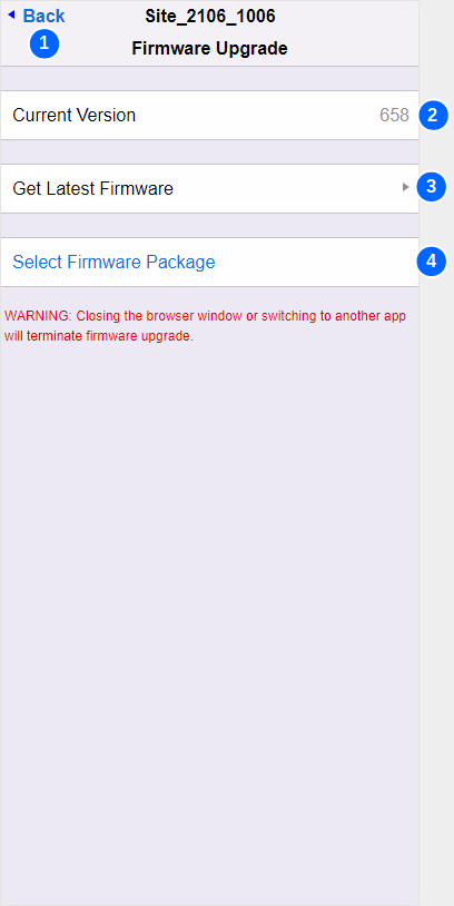
| No. | Name | Description |
|---|---|---|
| 1 | Back | Navigates back to the Utilities menu. |
| 2 | Current Version | Displays the Firmware Version currently installed. |
| 3 | Get Latest Firmware | The will open the official "Mpec firmware dowloads page" in a new boweser window. 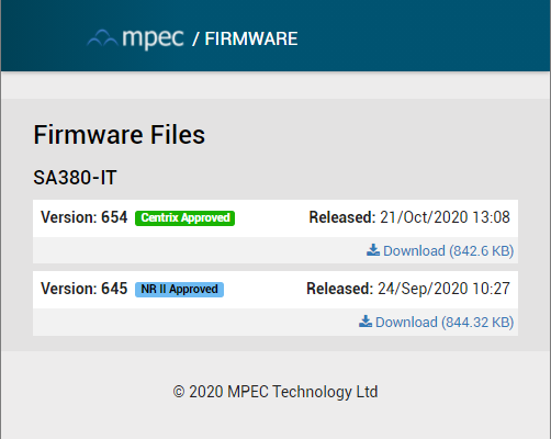
|
| 4 | Select Firmware Package | Select a firmware package previously downloaded. The user interface will differ between iPhone and standard web-browser. 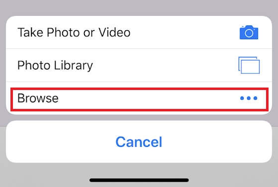 iPhone - find firmware files by selecting browse. Mac/PC - Use the standrad finder/file explorer interface.
Once a valid firmware package is selected, the user interface will update. (see below) |

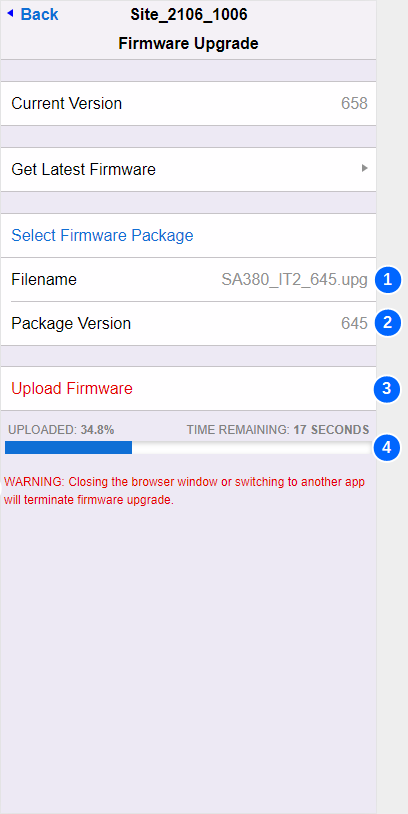
| No. | Name | Description |
|---|---|---|
| 1 | Filename | Displays the filename of the selected firmware package |
| 2 | Package Version | Displays the official firmware version of the selected package. |
| 3 | Upload Firmware | Once activated, upload of the new firmware package to the SA380-IT will begin. |
| 4 | Progress Bar | Displays the current progress of the firmware upload process. Do not navigate away from the firmware update page during the firmware upgrade operation. This will terminate the upgrade process. Once upload if complete, the SA380-IT will restart in order to complete the programming cycle. You may need to reconnect after reboot if using bluetooth. |
5.10) Settings
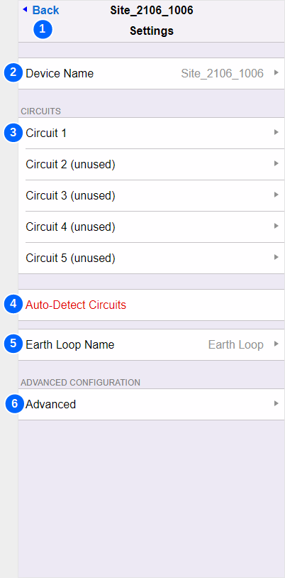
| No. | Name | Description |
|---|---|---|
| 1 | Back | Navigates back to the main menu |
| 2 | Device Name | You may change the name of device. The device name is displayed on all diagnstics tool pages and in your Enterprise Asset Managemet System. |
| 3 | Circuit Settings | To configure each of the five input circuits, select the circuit of interest here. |
| 4 | Autodetect Circuits | Autodetct Circuits runs a setup "wizard" to enable rapid comissioning of the SA380-IT. The detailed operation of Autodetect Circuits is found below. The Autodetect process will reset any active device interlocks. Ensure that any active interlocks have been investigated prior to proceeding. |
| 5 | Earth Loop Name | You may change the name of the "Earth Loop" channel here. This will change the display name of the "Earth Loop" channel in Live Measurements and in your Enterprise Asset Managemet System. |
| 6 | Advanced | Provides access to Advanced Settings that do not typically need to be altered in the vast number of installations. |
5.11) Circuit Settings
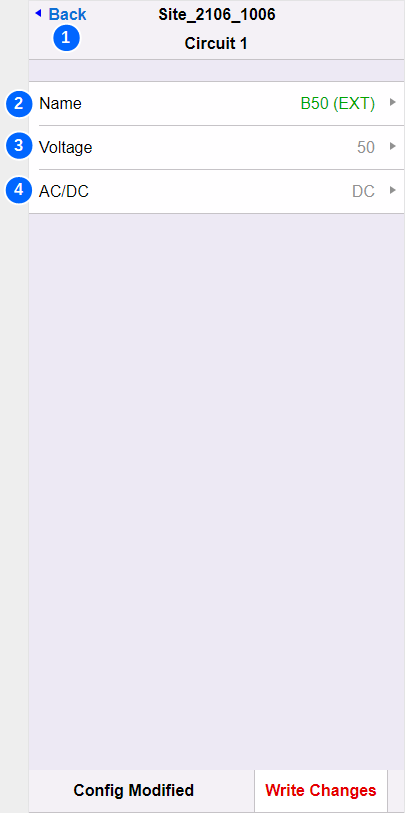
| No. | Name | Description |
|---|---|---|
| 1 | Back | Navigates back to the Settings menu |
| 2 | Name | You may change the name of the circuit here. This will change the display name of the circuit in Live Measurements and in your Enterprise Asset Managemet System. |
| 3 | Voltage | The nominal voltage of the monitored circuit. Nominal voltage is used to drive important safety features of the SA380-IT It is important that this is set correctly. Nominal voltage may be set incorrectly due to:
Enter a nominal voltage that aligns with typical measured voltage of the circuit in question: |
| 4 | AC/DC | Select if the monitored circuit is AC or DC. The AC/DC setting changes:
Setting this incorrectly may produce misleading data that can compromise system safety. |
5.12) Auto-Detect Circuits
| No. | Name | Description |
|---|---|---|
| 1 | Back | Navigates back to the Settings menu |
| 2 | Detected Voltage | Green text denotes that a valid voltage has been detected on this input channel and that a circuit has been configured for measurement. |
| 3 | Measured Voltage | The type (AC or DC) and magnitude of the voltage measured during the autodetect process. |
| 4 | Nominal Voltage | Shows the nominal voltage auto-configured for this circuit. The Autodetect process will attempt to match the measured voltage to the nearest common "railway" voltage.
Nominal voltage is used to drive important safety features of the SA380-IT It is important that this is set correctly. Nominal voltage may be set incorrectly due to:
Enter a nominal voltage that aligns with typical measured voltage of the circuit in question: |
| 5 | Reverse Voltage | Red text denotes a DC circuit that has been connected with incorret polarity. This circuit will not be configured and must be corrected. |
| 6 | Unused Circuit | Input channels with no voltage present will not be configured for measurement when using Autodetect. |
5.13 Advanced Settings
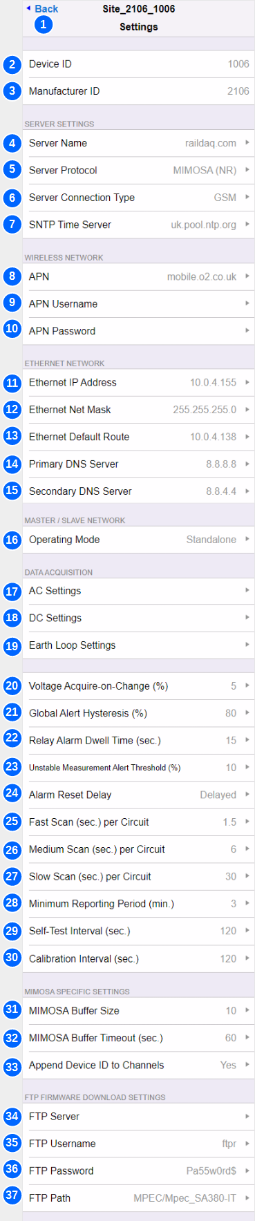
| No. | Name | Description | ||||||
|---|---|---|---|---|---|---|---|---|
| 1 | Back | Navigates back to the Settings menu | ||||||
| 2 | Device ID | Set to the device serial number. This is for information only. It cannot be changed. | ||||||
| 3 | Manufacturer ID | Mpec's unique SA380-IT manufacturer ID used by the Network Rail MIMOSA protocol only. This is for information only. It cannot be changed. | ||||||
| 4 | Server Name | The hostname or IP address of the Enterprise Asset Management system you wish to connect to. Common Server Names:
Default Server: raildaq.com The default server is a public server managed by Mpec. It is not intended for use with "live" deployed SA380-IT devices. The default "raildaq.com" server provides a place for orphaned SA380-IT devices that have lost their configration to connect to. This allows Mpec to support such devices. | ||||||
| 5 | Server Protocol | See Data Acquisition section for more detail.
| ||||||
| 6 | Server Connection Type | How to attempt data connection to the server system:
| ||||||
| 7 | SNTP Time Server | The name of a viable Simple-Network-Time-Protocol server. The SA380-IT will attempt to reach this server in order to set the time on the device at boot, and then once every hour. If connected to a MIMOSA server, you may find that the SNTP time server field has been overwritten at the request of the MIMOSA server. This is because MIMOSA servers instruct which time server the field device is to use. If connected to a RailDAQ server, the SNTP time service is not strictly required, and the field may be left blank. The default SNTP time server is resolvable on the public Internet. LAN / APN firewalls may prevent this being resolvable. | ||||||
| 8 | APN | Access-Point-Name. The APN is the name of the gateway between the GSM modem and a computer network. The APN is provided by your SIM provider and dictates which network you connect to. Common APNs:
The default APN allows connection to the public Internet on the O2 celluar network. The default APN allows orphaned SA380-IT devices that have lost their configration to connect back to Mpec. This allows Mpec to support such devices. | ||||||
| 9 | APN Username | Some APNs require a valid username in order to permit connection to a data network. The APN username will be provided by your SIM provider. | ||||||
| 10 | APN Password | Some APNs require a valid password in order to permit connection to a data network. The APN password will be provided by your SIM provider. | ||||||
| 11 | Ethernet IP Address | The IP address of the SA380-IT on the Ethernet interface. The IP address must be compatible with your local network settings, including:
The SA380-IT does not support DHCP. IP settings must be configured manually. The default IP address of the device upon shipment is: 192.168.100.115 | ||||||
| 12 | Ethernet Net Mask | Ethernet Subnet Mask: Used to define the network subnet of the LAN to which the SA380-IT is connected. The subnet mask must be compatible with your local network settings, including:
The SA380-IT does not support DHCP. IP settings must be configured manually. The default subnet mask of the device upon shipment is: 255.255.255.0 | ||||||
| 13 | Ethernet Default Route | Used to define the default network gateway (route) between the SA380-IT subnet and the wider LAN / Internet. The defualt route must be compatible with your LAN network settings to enable the SA380-IT to reach your Enterprise Server. The SA380-IT does not support DHCP. IP settings must be configured manually. The default route of the device upon shipment is: 192.168.100.1 | ||||||
| 14 | Primary DNS Server | Primary Domain Name Server. 1st Choice name server to use to resolve SNTP and Server hostnames into IP addresses. The domian name server must be compatible with your LAN network settings to enable the SA380-IT to reach your Enterprise Server. The SA380-IT does not support DHCP. IP settings must be configured manually. The default primary DNS server will be resolvable when connected to the public Internet. | ||||||
| 15 | Secondary DNS Server | Secondary Domain Name Server. 2nd Choice name server to use to resolve SNTP and Server hostnames into IP addresses. The domian name server must be compatible with your LAN network settings to enable the SA380-IT to reach your Enterprise Server. The SA380-IT does not support DHCP. IP settings must be configured manually. The default secondary DNS server will be resolvable when connected to the public Internet. | ||||||
| 16 | Operating Mode |
| ||||||
| 17 | AC Settings | Opens a menu that governs advanced setting regarding AC circuit data acquisition. | ||||||
| 18 | DC Settings | Opens a menu that governs advanced setting regarding DC circuit data acquisition. | ||||||
| 19 | Earth Loop Settings | Opens a menu that governs advanced setting regarding Earth Loop data acquisition. | ||||||
| 20 | Voltage Acquire-on-Change (%) | Governs the sensistivity of voltage data acquisition on all circuits. A new sample will be acquired whenever the voltage on a given circuit is observed to have changed by more than n% of it's previous reading. At low circuit voltages, acquisition is limited to changes no smaller than 0.1 V to prevent high data volumes. | ||||||
| 21 | Global Alert Hysteresis | Governs a hysteresis window for Earth-Loop out-of-tolerance state. For instance, if the earth loop out-of-tolerance level is set to 1,000 Ω and hysteresis is to set to 10%, then an out-of-tolerance earth loop reading must return to 900 Ω or less before the alert condition may clear. Alert clearance is sill subject to the alarm reset conditions also being satisfied. Network Rail MIMOSA mode only Governs a hysteresis window for DC Offset on AC Circuit Threshold. For instance, if DC Offset on AC Circuit Threshold is set to 11% and hysteresis is to set to 10%, then the level of DC offset on an AC circuit must return to 9.9% of the test-pulse signal level, or less before the alert condition may clear. Alert clearance is sill subject to the alarm reset conditions also being satisfied. | ||||||
| 22 | Relay Alarm Dwell Time (Sec.) | Governs the minimum operation time of the volt-free contact output. A minimum operation time is specified to prevent:
| ||||||
| 23 | Unstable Measurement Alert Threshold (%) | Network Rail MIMOSA mode only The SA380-IT tracks the percentage of failed measurements over a given reporting period on each circuit using Mpec's propriatary transient detection technology. If the percentage of failed measurements in a reporting period exceeds this thresold, then the UNSTABLE MEASUREMENT status-bit is set for the effected circuit and sent to the server. | ||||||
| 24 | Alarm Reset Delay | Governs the recovery process for non-critical device interlocks (alarm conditions) Measurement of input circuits will recommence under the following circumstance:
See Principals of Operation for a full discription of non-critical device interlocks | ||||||
| 25 | Fast Scan (Sec. per Circuit) | This setting is obsolete and scheduled for removal. The setting does not govern anything. | ||||||
| 26 | Medium Scan (Sec. per Circuit) | Network Rail MIMOSA mode only If measurement time of an individual circuit exceeds the medium scan setting, the Long Scan Mode status bit is set for the effected circuit and sent to the server. | ||||||
| 27 | Slow Scan (Sec. per Circuit) | Network Rail MIMOSA mode only If measurement time of an individual circuit exceeds the long scan setting, the Time Out status bit is set for the effected circuit and sent to the server. | ||||||
| 28 | Mimimum Reporting Period (Mins.) | Governs:
| ||||||
| 29 | Self-Test Interval (secs.) | The number of seconds between self-test cycles. Sets the maxium period a fault can exist prior to detection. Increased frequency has a marginal impact on device responsiveness. | ||||||
| 30 | Calibration Interval (secs.) | The number of seconds between calibration cycles. Increased frequency has a marginal impact on device responsiveness. Reduced frequency has a marginal impact on accuracy. | ||||||
| 31 | MIMOSA Buffer Size | Network Rail MIMOSA mode only Controls how many samples to buffer before constructing a MIMOSA message. Waiting for messages to buffer increases coms efficiency, but incurs a delay in sending data to the server. Buffer size controls how efficiently the data packets can be assembled. It is recomended to not exceed a setting of 20 samples, and this is the maximum number of samples that the SA380-IT can combine into a single MIMOSA message. | ||||||
| 32 | MIMOSA Buffer Timeout (secs.) | Network Rail MIMOSA mode only Controls how long messages can wait in the messaging buffer before constructing a MIMOSA message. Waiting for messages to buffer increases coms efficiency, but incurs a delay in sending data to the server. Buffer timeout limits this delay. | ||||||
| 33 | Append Device ID to Channels | The operation of the Network Rail II/RADAR server makes it diffcult to ascertain which field device a data channel belongs to. Appending the device ID to each channe name eases idintification of data channels is this server system.
| ||||||
| 34 | FTP Server | Network Rail MIMOSA mode only The hostname of the Network Rail II/RADAR FTP server for firmware upgrade. The SA380-IT will attempt to connect to this server upon start-up, and the between 2 AM and 4 AM UTC each day. If connection is succesful and new firmware is found, device firmware will be automatically downloaded and installed. Automated FTP firmware upgrade is only supported in Network Rail MIMOSA mode. No FTP upgrade attempt will be made in RailDAQ mode. Automated FTP firmware upgrade attempts can be inhibited by setting the field to be blank. | ||||||
| 35 | FTP Username | Network Rail MIMOSA mode only The FTP server requries a username. This is specified by the FTP server administrator. | ||||||
| 36 | FTP Password | Network Rail MIMOSA mode only The FTP server requries a password, This is specified by the FTP server administrator. | ||||||
| 37 | FTP Path | Network Rail MIMOSA mode only This specifes the "file path" on the FTP server in which to look for new SA380-IT firmware. This is specified by the FTP server administrator. |
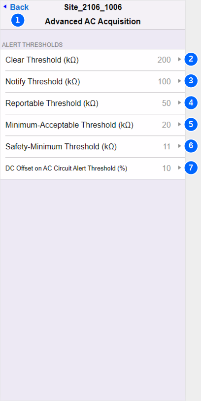
5.14) AC Settings
| No. | Name | Description |
|---|---|---|
| 1 | Back | Navigates back to the Advanced Settings menu |
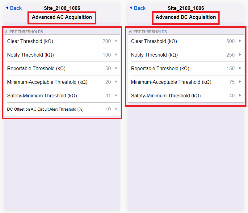
| 2 | Clear Threshold | AC Circuits - Network Rail MIMOSA mode only A level at which to trigger an "Acquire on threshold breach" measure of resistance-to-earth, where measured resistance is observed to have transitioned across the clear threshold in the rising direction. |
| 3 | Notify Threshold | MIMOSA and RailDAQ Modes:
The EARTH FAULT indication will extinguish if all circuits record a a resistance-to-earth above the notify threshold AC Circuits - Network Rail MIMOSA mode only A level at which to trigger an "Acquire on threshold breach" measure of resistance-to-earth, where measured resistance is observed to have transitioned accross the notify threshold in either a rising or falling direction. |
| 4 | Reportable Threshold | MIMOSA and RailDAQ Modes:
The EARTH FAULT indication will illuminate if any circuit records a resistance-to-earth below the reportable threshold AC Circuits - Network Rail MIMOSA mode only A level at which to trigger an "Acquire on threshold breach" measure of resistance-to-earth, where measured resistance is observed to have transitioned accross the reportable threshold in either a rising or falling direction. |
| 5 | Minimum Acceptable Threshold | AC Circuits - Network Rail MIMOSA mode only A level at which to trigger an "Acquire on threshold breach" measure of resistance-to-earth, where measured resistance is observed to have transitioned accross the minimum acceptable threshold in either a rising or falling direction. |
| 6 | Saftey Minimum Threshold | AC Circuits - Network Rail MIMOSA mode only A level at which to trigger an "Acquire on threshold breach" measure of resistance-to-earth, where measured resistance is observed to have transitioned accross the safety minimum threshold in the falling direction. |
| 7 | DC Offset on AC Circuit Threshold | AC Circuits - Network Rail MIMOSA mode only A level of common-mode voltage observed on AC circuits relative to the applied measurement pulse voltage (13 V), as observed during resistance-to-earth measurement. If this level is exceeded, the DC obsserved on AC bubar status bit is set for the affected circuit. |


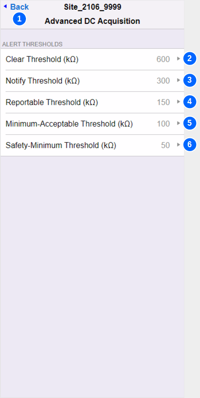
5.15) DC Settings
| No. | Name | Description |
|---|---|---|
| 1 | Back | Navigates back to the Advanced Settings menu |
| 2 | Clear Threshold | DC Circuits - Network Rail MIMOSA mode only A level at which to trigger an "Acquire on threshold breach" measure of resistance-to-earth, where measured resistance is observed to have transitioned across the clear threshold in the rising direction. |
| 3 | Notify Threshold | MIMOSA and RailDAQ Modes:
The EARTH FAULT indication will extinguish if all circuits record a a resistance-to-earth above the notify threshold DC Circuits - Network Rail MIMOSA mode only A level at which to trigger an "Acquire on threshold breach" measure of resistance-to-earth, where measured resistance is observed to have transitioned accross the notify threshold in either a rising or falling direction. |
| 4 | Reportable Threshold | MIMOSA and RailDAQ Modes:
The EARTH FAULT indication will illuminate if any circuit records a resistance-to-earth below the reportable threshold DC Circuits - Network Rail MIMOSA mode only A level at which to trigger an "Acquire on threshold breach" measure of resistance-to-earth, where measured resistance is observed to have transitioned accross the reportable threshold in either a rising or falling direction. |
| 5 | Minimum Acceptable Threshold | DC Circuits - Network Rail MIMOSA mode only A level at which to trigger an "Acquire on threshold breach" measure of resistance-to-earth, where measured resistance is observed to have transitioned accross the minimum acceptable threshold in either a rising or falling direction. |
| 6 | Saftey Minimum Threshold | DC Circuits - Network Rail MIMOSA mode only A level at which to trigger an "Acquire on threshold breach" measure of resistance-to-earth, where measured resistance is observed to have transitioned accross the safety minimum threshold in the falling direction. |
5.16) Earth Loop Settings
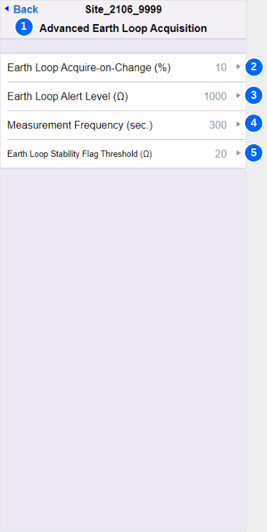
| No. | Name | Description |
|---|---|---|
| 1 | Back | Navigates back to the Advanced Settings menu |
| 2 | Earth Loop Acquire on Change | This setting is deprecated and will shortly be removed. The settings has no effect. |
| 3 | Earth Loop Alert Level | The SA380-IT will cease resistance-to-earth meseaurement if the earth-loop resistance exceeds this threshold. Resistance-to-earth meseaurement will recommence if the earth-loop resistance is lower than this threshold and the alarm reset conditions have been satisfied. MIMOSA and RailDAQ Modes:
The HW FAULT indication will illuminate if earth-loop resistance exceeds this threshold. Network Rail MIMOSA mode only This condition will set the Earth Loop Unstable flag. |
| 4 | Measurement Frequency | Governs how often earth-loop resistance measurements are performed. Sets the maxium period a fault can exist prior to detection. Increased frequency has a marginal impact on device responsiveness. |
| 5 | Earth Loop Stability Flag Threshold | The SA380-IT will cease resistance-to-earth meseaurement if the consecutive earth-loop resistance differ by a margin greater than this threshold. Resistance-to-earth meseaurement will recommence if consecutive earth-loop resistance readings differ by less than this threshold and the alarm reset conditions have been satisfied. MIMOSA and RailDAQ Modes:
The HW FAULT indication will illuminate if consecutive earth-loop resistance readings differ by more than this threshold. Network Rail MIMOSA mode only This condition will set the Earth Loop Unstable flag. |

5.17) About
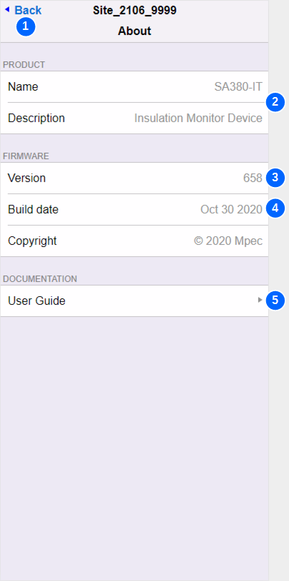
| No. | Name | Description |
|---|---|---|
| 1 | Back | Navigates back to the Main menu |
| 2 | Name & Decription | Lists the product name for information only |
| 3 | Version | Lists the current firmware version for information only |
| 4 | Build Date | Lists the firmware build date for information only |
| 5 | User Guide | A handy link to this documentation. |
6) Faulting and Maintenance
7) Principals of Operation
8) Data Acquisition
9) Technical Data
9.1) Specification Data
Insulation Coordination to EN50124-1 & EN60101-1 | ||
|---|---|---|
| Nominal System Supply Voltage (UN) (110 V AC Variant) | AC 110 V RMS | |
| Nominal System Supply Voltage (UN) (12 V DC Variant) | DC 12 V | |
| Over-voltage Category | CAT IV | |
| Rated Impulse Voltage Withstand (UNi) | 4 kV | |
| Pollution Degree | 3 | |
| Rated Insulation Voltage (UNm) | AC 185V RMS | |
| Inter-Monitored Circuit Isolation Voltage (Galvanic) | +/- 400 V Peak | Min. |
| Inter-Monitored Circuit Protective Impedance (in break-down) | 140 kΩ | Min. |
| All devices undergo factory Hi-Pot testing |
Supply Voltage | ||
|---|---|---|
| Operating Voltage Range (110 V AC Variant) | AC/DC 40-160 V RMS | +15% |
| Operating Frequency Range (110 V AC Variant) | DC to 60 Hz | |
| Operating Voltage Range (12 V DC Variant) | DC 10-16 V | +15% |
| Max. Power Consumption | 6 VA |
Monitored Circuits Voltage | ||
|---|---|---|
| Number of Independent Circuits Monitored | 5 | AC or DC |
| Operating Voltage Range | AC 5-160 V RMS DC 5-160 V RMS | +15% +15% |
| Operating Frequency Range | DC to 60 Hz | |
| Voltage Accuracy | +/- 5 % | >= 1 V |
Monitored Circuits Insulation Resistance | ||
|---|---|---|
Equivalent Resistance to Earth (RL = RB//RN) | 0 Ω to 5 MΩ | AC Circuits |
Actual Resistance to Earth (RB and RN) | 0 Ω to 5 MΩ | DC Circuits |
| Accuracy* | +/- 1 kΩ | ZL < 20 kΩ |
| +/- 5 % | ZL >= 20 kΩ ZL <= 1 MΩ | |
| Alarm Response Value | Configurable 1 kΩ to 1 MΩ | Factory set at: 150 kΩ for DC 50 kΩ for AC |
| Alarm Hysteresis | Configurable 1 kΩ to 1 MΩ | Factory set at: +150 kΩ for DC +50 kΩ for AC |
| Standard Response Time (per circuit) TR | 1.5 s | Typical |
Maximum Response Time (per circuit) TR | 750,000 x CE | seconds |
| Product Response Time | TR X Number of Circuits in Operation | Typical |
System Leakage Capacitance (CE) (per circuit) | 100 μF | Max. |
*See section ? for an explanation of measurement accuracy with regard to the insulation resistance of DC monitored circuits.
Measuring Circuit | ||
|---|---|---|
| Measuring Voltage | +/- 13 V | |
| Measuring Current | < 200 μA | |
| Internal Resistance & Impedance | > 45 kΩ | no resistive cable fitted |
| System Resistance & Impedance | > 70 kΩ | resistive cable fitted |
Measuring Circuit is only connected to a single Monitored Circuit at any one time | ||
| Internal System Check Frequency | 300 s |
Earth Loop Circuit | ||
|---|---|---|
| Measuring Voltage | +/- 3.5 V | Max. |
| Measuring Current | < 1 mA | |
| System Resistance & Impedance | > 25 kΩ | FE to SE |
| Tolerance to Stray Interference Voltage | +/- 1,100 mV DC. | |
| +/- 850 mV AC. | Peak, | |
| Measurement Range | 0 Ω to 1.1 kΩ | |
Accuracy | +/- 0.5 Ω | RE < 10 Ω |
| +/- 5 % | RE >= 10 Ω | |
| Alarm Value | Configurable 0 Ω to 1 kΩ | Factory set at 1 kΩ |
| Alarm Hysteresis | Configurable 0 % to 100 % | Factory set at 10 % |
Output Ports & Radio | ||
|---|---|---|
| Auxiliary Power Output | Voltage | 5 V +/- 10 % |
| Power | 1 W +/- 10 % | |
| Volt-Free Contact | Form | N.O. SPST |
| Withstand Voltage | +/- 160 V Max. | |
| Contact On Resistance | 0.75 Ω Max. | |
| Contact Off Resistance | 1 MΩ Min. | |
| Max. Current | 1 A AC RMS or DC | |
Serial Data Output | EIA RS485 | 115,200 bps Max. |
| Ethernet | RJ45 | 10/100 Mbps Auto MDIX |
| Wireless Modem (SIM Factory Fitted) | SMA (Female) | GSM 2G GPRS |
| Bluetooth | Touch to Enable | Bluetooth Low Energy |
Supported Protocols | ||
|---|---|---|
MPEC RailDaq Efficient Data Communications | LAN/GSM RS485 | TCP/IP Port 7777 112,800 bps |
Network Rail MIMOSA Verbose Data Communications | LAN/GSM | TCP/IP Port 80 |
SNTP Time Synchronization | LAN/GSM | UDP Port 123 |
HTTP Configuration and Live Data | LAN/GSM | TCP/IP Port 80 |
FTP Firmware Upgrade for NR users | LAN/GSM | FTP Port 21 (Outbound) FTP Port 1024–65535 (Inbound) |
Environmental | ||
|---|---|---|
EMC Emissions & Immunity | EN50121-4 | |
Surge Immunity: Monitored Circuits & Earth | EN61000-4-5 | 4kV |
Voltage Withstand | EN50124-1 EN61010-1 | |
| Climatic Class | EN50125-3 | T1 In cubicle |
Ambient Operating Temperature | -25 °C to +70 °C | |
| Storage Temperature | -40 °C to +85 °C | |
| Humidity | 5 % to 100 % | Condensing |
| Vibration | 2.3 m/s2 | 3 - axis' |
| Impact Protection | IK06 | |
| Ingress Protection | IP52 | |
| Flammability Rating | UL94 V0 |
Installation Data | ||
|---|---|---|
Mounting | BR930 / Q Style Mounting Plate | |
Primary Connections | Wire Size: 2.5 mm2 max. | Spring Clamp |
Auxiliary Connections | Wire Size: 1.5 mm2 max. | Spring Clamp |
| Weight | 350g |