VTi21 Configuration
- Mark Beeson (Deactivated)
- Oliver Skidmore (Unlicensed)
- Mark Lock
Configuration for 4-20mA
The sensor can be used as a 4-20mA sensor connected to either an SA380 TX, SA380TX-L, or indeed any COTS data logging device that supports 4-20mA inputs.
The sensor range, and engineering unit will differ, dependent upon the application firmware loaded onto the VTi21. Consult the full sensor table for further information.
Despite this the general process for configuring the sensor for 4-20mA use remains the same between variants.
SA380 TX-L
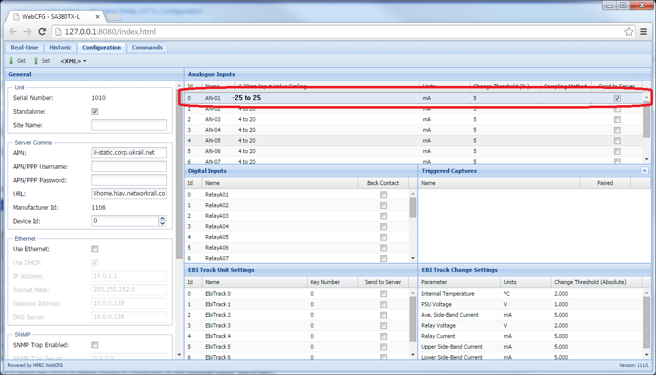
Using dPanel, or via an IP connection, the following illustrates the settings required for the 4-20mA inputs. The example here uses the settings for a -VT1 connected to Analogue Input 1.
SA380 TX
Using the Touch screen
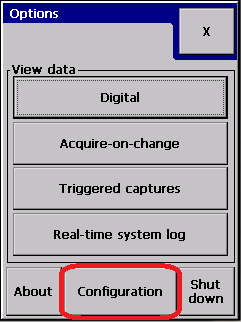
Enter Configuration Menu, entering logger password when prompted

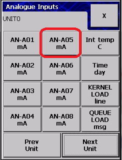
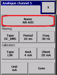
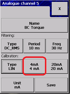
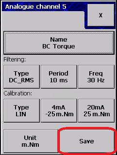
Select Analogue setup, select the channel to which the output is connected (in the example below, this is AN5).

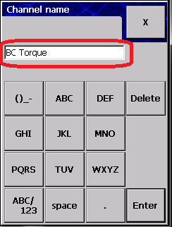
Change the name to something appropriate, eg. "BC Torque" for BC track circuit relay:
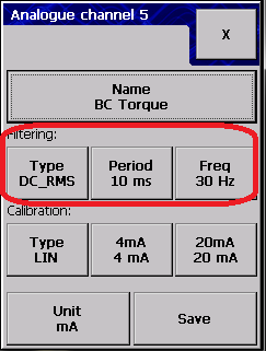
Filtering:
Filter Settings can usually remain unchanged - Consult SA380TX documentation for further information regarding filter settings.
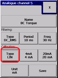
Calibration:
Press the "Type" button until "LIN" is displayed (meaning linear sensor).
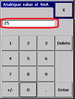
Press the "4mA" button and enter the sensor output quantity at 4mA. For the -VT1, this is 0 (contrary to the screenshot).
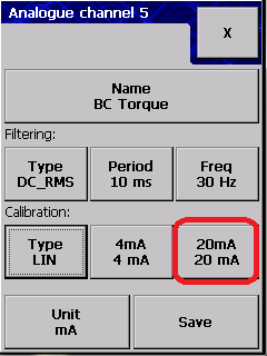
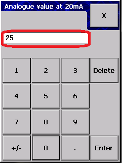
Press the "20mA" button and enter the sensor output quantity at 20mA. For the -VT1, this is +25.
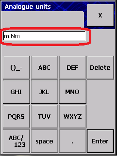
Press the "Units" button and enter the sensors engineering units. For the -VT1, this is m.Nm (Milli-Newton-Meters).
The above values will vary dependant upon variant. Consult the table below for variant dependent settings

Once configured, select save.
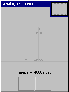
Your sensor is now configured and live data will now be visible on the real-time analogue display.
To enable data acquisition you must configure an "Acquire-on-Change", "Triggered Capture" or "Rail Event".
Using the Web Configuration tool
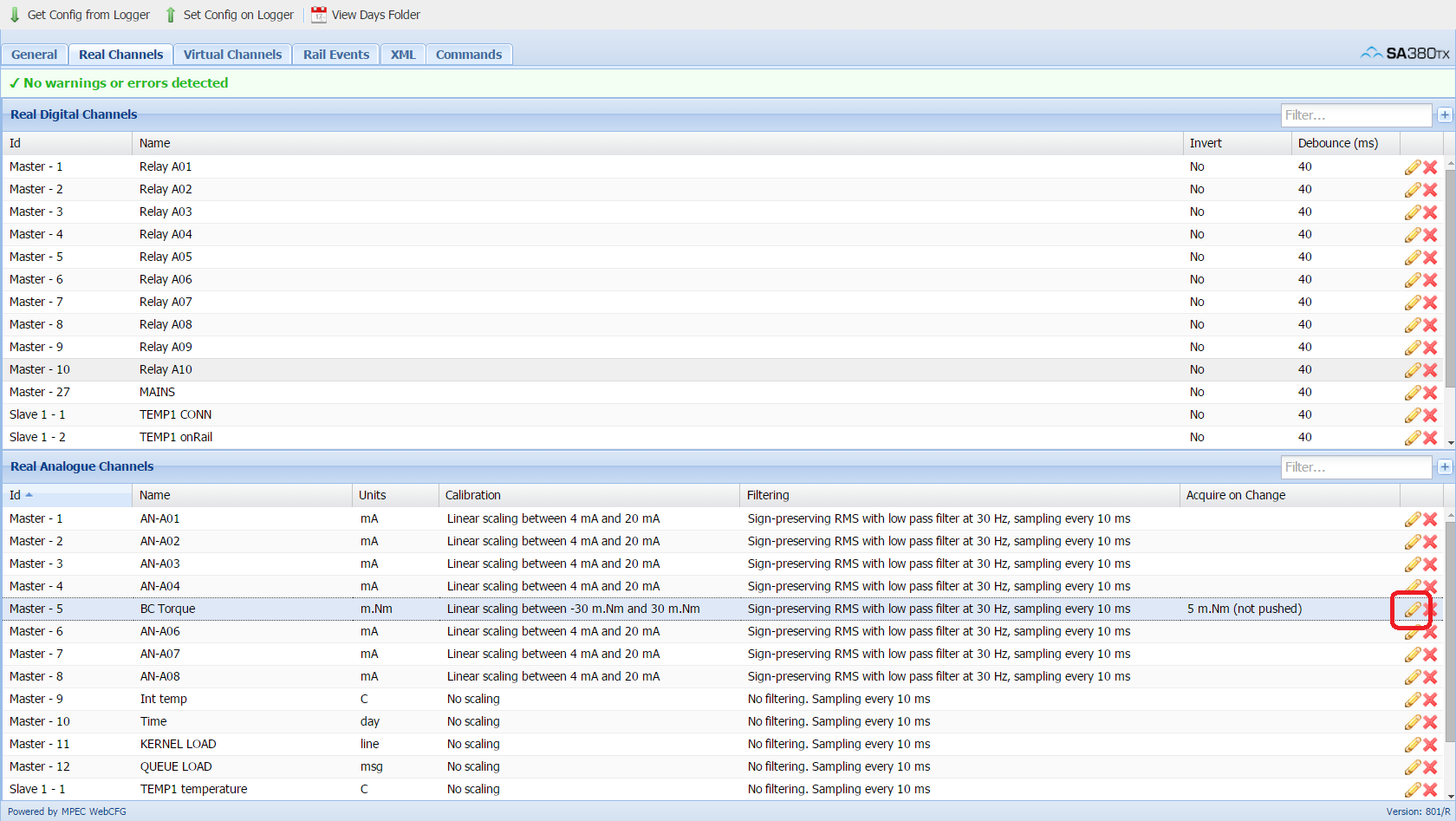
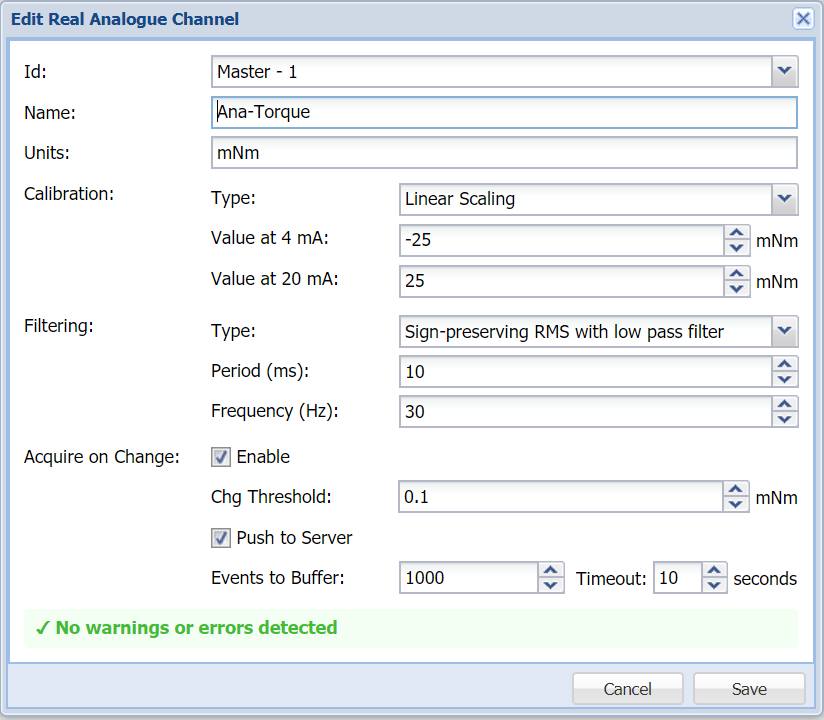
All channel settings can be configured from a single dialog box. Click the pencil icon on the connected channel to open this dialogue. Sensor settings are as described above.
Configuration on RS485
The RS485 interface is available for use with an SA380 TX. It provides additional information above and beyond the 4-20mA interface for all variants. A full table detailed which parameters are available for each variant is shown here.
detection from the touch screen
The logger is configured as a slave unit to the SA380 TX.
Slave configuration is described in detail in the "howto" entitled "SA380 TX Master with TX-L & Slaves using RS485".
The following illustration briefly shows how this can be done.
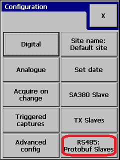
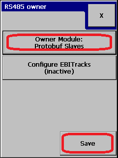
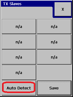
From the configuration screen, you need to tell the logger that it has RS485 slaves (press the Owner module button until it says "Protobuf Slaves"):
Now run run the auto-detect routine. This will search the RS485 bus for connected slave loggers, and populate the loggers configuration with their details:
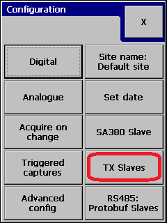
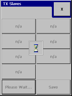
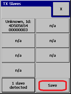
An hour glass will appear, and after a few seconds the logger should display the slave(s) found, and their serial number:
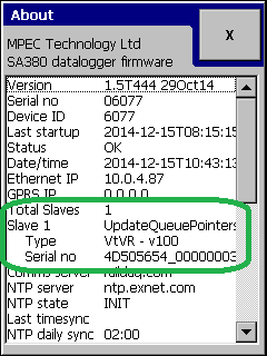
You can verify that the sensors are connected by using the about display (accessed by pressing Menu | About on the touch screen):
Sensor configuration from the touch screen
Slave configuration from Web Config
Configuration from the web configuration tool is reliant on two sections being filled in.
Firstly the slave logger needs configuring from the "General" tab. This is shown below.

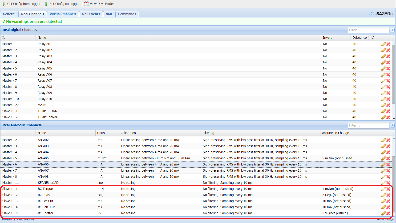
Secondly, the "Real Analogue Channels" section under the "Real Channels" tab: