SA380TX-L Unit Configuration
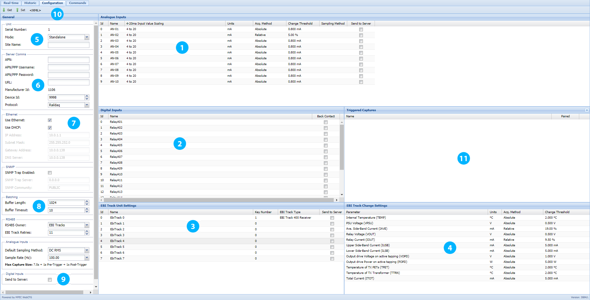
All unit configuration is performed using this screen.
Analogue
1. Analogue
Analogue Channel Name - A descriptive name for the channel. E.g. “AA T" for AA tracks circuit, or “701 WI” for 701 points motor current.
For NR II monitoring use the naming scheme suggested above.
Sensor Scaling - Calibrates the logger input for a particular sensor type.Scaling Type: Choose Linear, Quadratic, or Inverse Quadratic
For Linear Sensors.....
Value @ 4mA: The measurement value when your sensor is outputting 4mA. (Typically the lowest measured value.)
Value @ 20mA: The measurement value when your sensor is outputting 20mA. (Typically the highest measured value.)
For Quadratic Sensors.....
Values a,b and c: The coefficients of the polynomial equation y = (ax2) + (bx) + c, where y is the output value, and x is the 4-20mA input value.
For Inverse Quadratic Sensors.....
Values a,b and c: The coefficients of the polynomial equation y = (a / x2) + (b / x) + c, where y is the output value, and x is the 4-20mA input value.
For a RoweHankins 600 mA CT, use linear scaling and enter “0” and “600” in these two fields respectively.
For a LEM 20 A CT, use linear scaling and enter “0” and “20” in these two fields respectively.
For a LEM 30 A CT, use linear scaling and enter "-30" and "+30" in these two fields respectively.
Units - Enter the Engineering units of the sensor you are using:
E.g. (V for Volts, mA for milliamps, N for Newtons etc.)
For a RoweHankins 600mA CT, enter “mA” in this field.
For a LEM 20 A CT, enter “A” in this field.
Change Threshold - If Acq. Method is set to Relative, this number determines the percentage change relative to the last acquired value required to trigger the acquisition of a sample.
If Acq. Method is set to Absolute, this number governs the absolute change in signal level required to trigger acquisition of a sample.
For NR II DC track circuit monitoring a change threshold of 6 mA absolute has been suggested.
Sampling Method: - If "blank", then the sampling method listed in Section 8 applies to this channel.
- If an alternate sampling method is desired for this channel only, then select this here.
- Sampling Methods are described in detail in the applications section of the user guide.
For NR II applications, leave this field "blank"
Send To Sever - When unchecked data is stored locally. When checked data is sent to the designated server and data is stored locally.
For NR II track circuit monitoring “Send to Server” must be checked on active channels.
For NR II point monitoring “Send to Server” should be unchecked on active channels.
Digital
2. Digital
Digital Channel Name - A descriptive name for the channel. E.g. “701 NKR” for 701 points normal detection relay.
Back Contact - Leave unchecked if monitoring a spare front relay contact.
Check the box if monitoring a spare back relay contact.
EBI Track
3. Unit Settings
Tell the TX-L what EBI Track units are connected to the data logger.
Unit Name - A descriptive name for the EbiTrack unit. E.g. “AA T Rx" for AA track circuit receiver, or “AA T Tx” for AA track circuit transmitter
Key Number - EbiTrack units are “addressed” via the key serial number printed on the data key inserted into each EbiTrack unit.
Entering a key number here instructs the TX-L to monitor the EbiTrack unit that matches this key number.
A key number of “zero” instructs the TX-L not to monitor any EbiTrack unit.
Send to Server - When unchecked data is stored locally. When checked data is sent to the designated server and data is stored locally.
4. Change Settings
These settings dictate how sensitive the “Acquire-on-change” settings are for all monitored EbiTracks.
Parameter / Units - These fields are fixed for EbiTrack monitoring and cannot be changed
Change Threshold - Change the acquisition sensitivity of each channel in these fields.
- If Acq. Method is set to Relative, this number determines the percentage change relative to the last acquired value required to trigger the acquisition of a sample.
- If Acq. Method is set to Absolute, this number governs the absolute change in signal level required to trigger acquisition of a sample.
The default settings are suitable for NR II EbiTrack 200 applications.
Where EbiTrack 400 Receivers are to be monitored, it is suggested that IAVE is set to 10% Relative due to the variance in set-up current levels.
General
5. Unit
High level unit settings for the TX-L
Serial Number - Identifies the unit serial number. This value is read-only.
Site Name - Human readable identifier of the TX-L’s location.
Mode - Select "Stand-alone" from the drop-down menu if the SA380TX-L is a stand-alone unit. Select "Slave" if the unit is to be used as "slave"
6. Server Comms
Settings to allow the logger to communicate with the data collection server.
APN / APN Username / APN Password - These fields contain settings to allow cellular network connection.
Server URL - The web address of your data collection server.
Device ID - A numeric ID unique to this logger on the condition monitoring network.
Protocol - Select a Protocol compatible with your chosen Enterprise Condition Monitoring System
| Supported by Network Rail II | Supported by Mpec Centrix | Compact Size | Human Readable | Supports Datalogger Level Diagnostics | Supports Communications Level Diagnostics | Allows Remote Upgrade & Configuration | Automated Logger Deployment | |
|---|---|---|---|---|---|---|---|---|
| MIMOSA | Y | Y | Y | |||||
| RailDAQ | Y | Y | Y | Y | Y | Y |
7. Ethernet
Settings to control the networking behaviour of the unit.
Use Ethernet - Turns ON the Ethernet card (if present). Will turn OFF the GSM modem.
Use DHCP - With DHCP turned on, the network will determine the units IP address and override user settings.
IP Address - Assigns the unit a fixed IP address (Used when DHCP is disabled)
Subnet Mask, Default Gateway, DNS Server
Advanced Ethernet settings can be changed here.
8. Batching
Settings to economise how analogue data is sent to the server.
Buffer Length - How many samples can be stored in memory prior to transmission to the server.
If this limit is reached before the timeout period elapses, samples are sent to the server immediately.
Buffer Timeout - “Buffer timeout “ sets how long to wait (in seconds) before sending a new sample to the server.
Subsequent samples recorded during this time period are “batched” together prior to sending, economising data traffic.
RS485 Owner - “Buffer timeout “ sets how long to wait (in seconds) before sending a new sample to the server.
Subsequent samples recorded during this time period are “batched” together prior to sending, economising data traffic.
EbiTrack Retries - Dictates how many "dropped" messages will be tolerated from an EbiTrack unit before deciding that the device is disconnected.
The default value of "11" guards against nuisance disconnect events with EbiTrack 400 Transmitters. These devices often drop packets due to conducted noise from the transmitter output
Default Sampling Method - Selects the default filtering method to be applied to all analogue channels. This setting can be overridden on per-channel basis (see section 1).
- The applications section of the user guide explains the various sampling methods in detail.
50 Hz DC Applications: Use DC RMS
50 Hz AC Applications: Use AC RMS
60 Hz DC Applications: Use DC RMS with Low-Pass Filter
60 Hz AC Applications: Use AC RMS with Low-Pass Filter
Sample Rate - The default sample rate of 100 Hz allows triggered capture of maximum length 9.5 seconds. If longer captures are desired, then the sample rate for the entire device can be reduced here. This is at the expense of data quality. The applications section of the user explains this in detail.
9. Sending Digitals - Toggles the transmission of digital events on or off.
At present NR II forbid the sending of digital data, set to ”False”.
Configuration Control
10. Configuration Control - The ability to save configs allows configuration management of all of your TX-L loggers and allows you to prepare configs prior to commissioning.
Get and Set - Click “Get” to retrieve the configuration from the connected logger.
Click “Set” to send the displayed configuration to the connected logger.
<XML> - Click “<XML>” to open the current configuration for the logger in XML format.
From this window the configuration can be saved and loaded.
It is not advisable that changes to the XML be made without guidance from MPEC or in-depth knowledge of the product.
Incorrect modification to any part of the XML can result the SA380TX-L data logger becoming unresponsive and non-operational.
Triggered Captures Overview
11. Triggered Captures Overview
Settings to allow you to create or edit “triggered captures”.
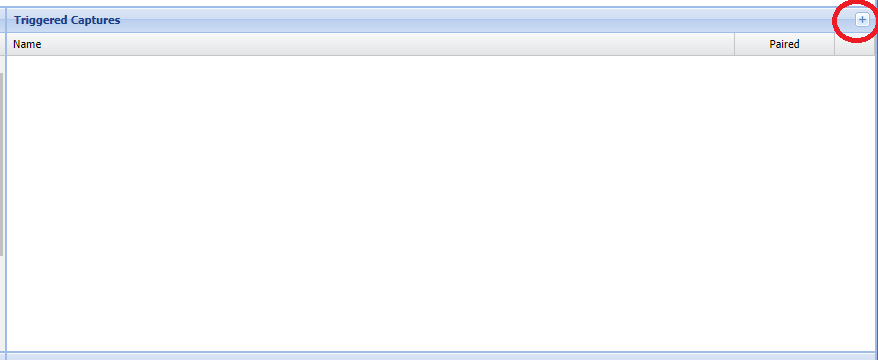
Adding a Triggered Capture - Add a capture by clicking the plus symbol in the top right of the "Triggered Captures" window.
This will bring up the "Add Tiggered Capture" dialog, which is decribed in detail later.
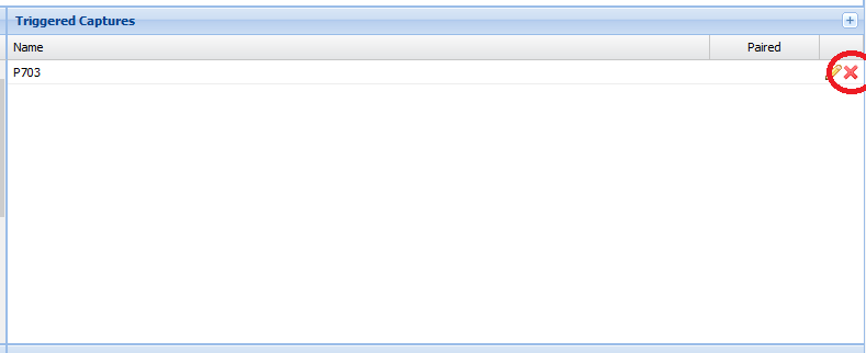
Editing a Triggered Capture - Edit an existing capture by clicking on the pencil symbol to the right of the capture you wish to edit.
This will bring up the “Edit Triggered Capture” dialog, which is described in detail later.
Please note: A maximum of 12 triggered captures can be created per logger.
Triggered Capture Configuration: Adding a Triggered Capture
Clicking the plus highlighed below creates opens the "Add Triggered Capture" dialog, to create a new capture if one is available. The logger supports up to 12 captures.
Use this dialog to configure your Triggered Capture Settings
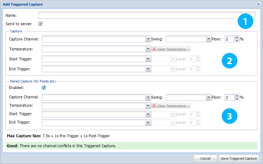
1. General Settings
Name your capture, select if it is to be transmitted to the central server and whether or not the capture is “paired”
Name - A descriptive name for the capture, e.g. “P701” for 701 points.
Send to Server - When unchecked data is stored locally. When checked data is sent to the designated server and data is stored locally.
2. Capture
These settings define how the capture is generated.
Where a “paired” capture has been selected, these settings are duplicated with the upper settings controlling one capture; whilst the lower settings control the paired “sister” capture.
Capture Channel - Select the analogue channel from which the waveform will be captured.
Note that the TX-L will automatically detect and invert any negative waveforms for you, allowing you to employ bi-directional CT’s.
Swing - Select if this capture is recording a move in the Normal to Reverse (N-R) or Reverse to Normal (R-N) direction.
For NR II point monitoring select N-R for the top capture and R-N for the bottom capture.
Floor - Prevent undesirable sensor noise from disrupting your capture by setting a “noise floor” level.
“Floor” is specified as a percentage of full-scale-deflection of the capture channel.
Temperature - This allows the selection of an additional analogue channel for the recording of temperature.
If a temperature sensor is connected to one of the loggers analogue channels, this can be selected here, so that temperature data can be captured along side the data collected from the capture channel, i.e. points motor current.
Ambient, rail and other temperature readings can be collected, depending on the sensor connected to selected analogue channel.
For NR II point monitoring, an example use may be capturing points motor current alongside the temperature of the rail.
Start Trigger - When the start trigger becomes true, data recording commences.
Note that data of interest will be automatically recorded up to 1 second prior to the start trigger.
The start trigger can be an analogue or digital event as described further below.
Stop Trigger - When the stop trigger becomes true, data recording ceases.
Note that data of interest will be automatically recorded up to 1 second after the stop trigger.
The stop trigger can be an analogue or digital event as described further below.
Digital Triggers Explained - Digital triggers can be set to fire on a transition from “Down to Up” or “Up to Down”.
Analogue Triggers Explained - Analogue triggers can be set to fire when the incoming signal is seen to rise above a set level (Greater Than), or when the incoming signal is seen
to fall below a set level (Less Than). The set level is to be entered in the neighbouring text box.
3. Paired Capture
A “paired” capture is required where the direction of movement of the monitored asset is deemed important.
A paired capture consists of two otherwise independent captures that are logically linked together.
An example of an asset requiring a non-paired capture would be a level crossing barrier, as the barrier only ever motors in one direction.
An example of an asset requiring a paired capture would be a point machine, as the points move in two distinct directions.
Twinned Captures for RADAR
The SA380TX-L is now compatible with both Centrix and RADAR hydraulic point monitoring solutions.
To ensure your installation is compatible with RADAR, simply follow these instructions during configuration:
Create two captures, one for pressure, one for current.
Ensure start and end triggers for both normal and reserve direction captures match exactly.
e.g. Red matches red, blue matches blue, green matches green and yellow matches yellow.
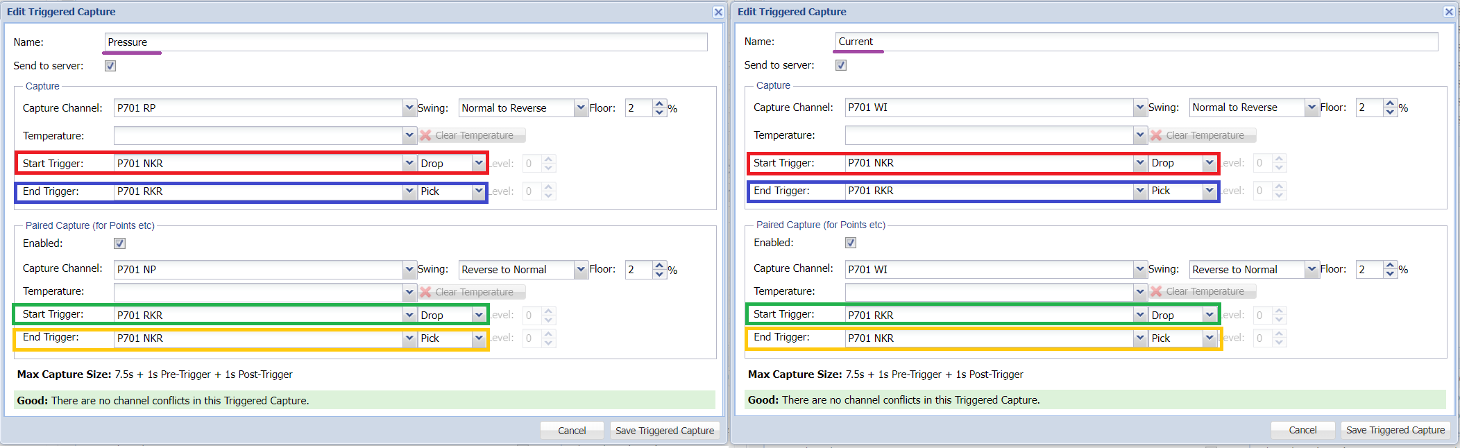
Doing the above ensure that captures are transmitted to the RADAR platform in form that the system can understand.
Triggered Capture Configuration: Editing a Triggered Capture
Clicking the pencil symbol highlighted below will open the "Edit Triggered Capture" dialog.
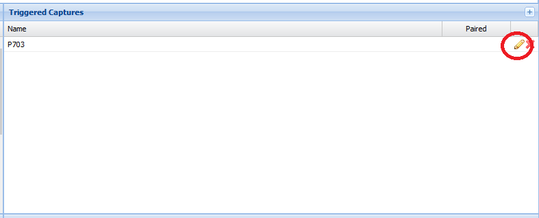
The "Edit Triggered Capture" dialog allows any of the settings applied when creating the capture to be edited.
If you wish to delete a capture, click the cross as highlighted below.