Using the SA380-IT to measure Isolation between two independent 12V DC Circuits
Overview
The SA380-IT may be used to measure the isolation between two independent circuits by wiring the device as shown below.
Wiring the Power supply to the unit into input number, one, via the "HI Z" terminals provides the benefit of measureing resistance to earth of this circuit, as well as the nominal voltage of the main supply circuit, which is likely the B12 circuit.
- At present, the SA380-IT measures the degree of isolation between circuits as a standing voltage between the two circuits being measured. A table (at the end of this document) must be utilised to determine the possible level of insulation resistance.
- Connecting both B12 and XB12 circuits in the standard arrangement adds the ability to monitor nominal circuit voltage and isolation from earth. This is important as a low nominal circuit voltage may mask an inter-circuit isolation fault due to lower than expected standing voltages.
Detectable Faults
Low Nominal Circuit Voltage
Monitoring the circuit voltage allows abnormally high, or abnormally low battery voltage to be detected. This is well documented in the existing user-guide.
- Detect failing battery cells or chargers
- Warning that inter-circuit isolation may be lower than suspected in the event of a low nominal voltage
Isolation from Earth
The SA380-IT is primarily designed to ensure supply circuit that are earth-free by design remain so, Connecting both B12 and XB12 in the normal arrangement ensures that this is true.
This is well documented in the existing user-guide.
Inter-Circuit Isolation
Device misoperation is also possible due to cross-coupling of circuits where the fault path is not via an earth connection.
By wiring SA380-IT inputs "cross-pole" between two circuits, a standing voltage on the SA380-IT inputs will be observed if any of the four fault conditions shown below are true.
The wiring diagram above shows this "cross-pole" arrangement on inputs 2 and 3.
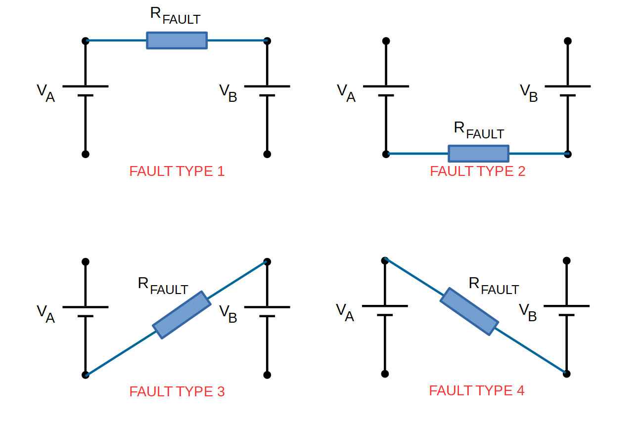
Fault 1 and Fault 2 cause a voltage to present across both of the SA380-IT inputs. In this scenario the voltage may be as high as the nominal circuit voltage.
The equation for translating the voltage into a resistance reading is shown below.
EQUATION 1: 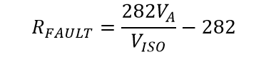
Where VA is the nominal circuit voltage (12 V)
and VISO is the standing voltage between circuits measured by the SA380-IT
For Reference, a table is provided at the end of this document to enable the operator to quickly look up a value.
Fault 3 and Fault 4 cause a voltage to present across one of the SA380-IT inputs only. In this scenario, the voltage may be as high as sum of the two circuit voltages.
The equation for translating the voltage into a resistance reading is shown below.
EQUATION 2: 
Where VA is the nominal circuit voltage of the 1st circuit (12 V)
and VB is the nominal circuit voltage of the second circuit(12 V)
and VISO is the standing voltage between circuits measured by the SA380-IT.
Fault 3 and Fault 4 cause a larger voltage to be presented to the SA380-IT than Fault 1 and Fault 2. All four faults can also present in any combination, however the voltages presented in the case of Fault 1 and Fault 2 represent a "worst case"
Equation 1 should therefore be used for the selection of alert levels and used to inform intervention decisions. The value yielded by equation 1 should there be read as "Resistance greater than or equal to X"
Equation 1 also assumes a nominal circuit voltage. A voltage of 11.4 volts has been used to produce the table below. If it is credible that the cell voltage could fall further, yet the circuit remains operable, then a different nominal voltage should be used to populate the table.
Configuration
If the wiring diagram above has been followed, the SA380-IT inputs should be configured as per the table below:
| Input No. | Name | Voltage | Type |
|---|---|---|---|
| 1 | B12 | 12 | DC |
| 2 | ISO 1 | 24 | DC |
| 3 | ISO 2 | 24 | DC |
| 4 | XB12 | 12 | DC |
Fault Resistance Table
Use the look up table below to convert the voltage present on either the "ISO 1" or "ISO 2" channels into a worst-case level of inter-circuit isolation.
The table is populated using Equation 1, using a nominal circuit voltage of 11.4 V
The resistance value stated is "worst-case" the true level of isolation resistance may be greater and will be dependant upon how the fault is manifest.
Measured Voltage (ISO 1 or ISO 2) | Insulation Resistance (>= k Ohm) |
|---|---|
| 0 | INF |
| 0.1 | 31866 |
| 0.2 | 15792 |
| 0.3 | 10434 |
| 0.4 | 7755 |
| 0.5 | 6148 |
| 0.6 | 5076 |
| 0.7 | 4311 |
| 0.8 | 3737 |
| 0.9 | 3290 |
| 1 | 2933 |
| 1.1 | 2641 |
| 1.2 | 2397 |
| 1.3 | 2191 |
| 1.4 | 2014 |
| 1.5 | 1861 |
| 1.6 | 1727 |
| 1.7 | 1609 |
| 1.8 | 1504 |
| 1.9 | 1410 |
| 2 | 1325 |
| 2.1 | 1249 |
| 2.2 | 1179 |
| 2.3 | 1116 |
| 2.4 | 1058 |
| 2.5 | 1004 |
| 2.6 | 954 |
| 2.7 | 909 |
| 2.8 | 866 |
| 2.9 | 827 |
| 3 | 790 |
| 3.1 | 755 |
| 3.2 | 723 |
| 3.3 | 692 |
| 3.4 | 664 |
| 3.5 | 637 |
| 3.6 | 611 |
| 3.7 | 587 |
| 3.8 | 564 |
| 3.9 | 542 |
| 4 | 522 |
| 4.1 | 502 |
| 4.2 | 483 |
| 4.3 | 466 |
| 4.4 | 449 |
| 4.5 | 432 |
| 4.6 | 417 |
| 4.7 | 402 |
| 4.8 | 388 |
| 4.9 | 374 |
| 5 | 361 |
| 5.1 | 348 |
| 5.2 | 336 |
| 5.3 | 325 |
| 5.4 | 313 |
| 5.5 | 303 |
| 5.6 | 292 |
| 5.7 | 282 |
| 5.8 | 272 |
| 5.9 | 263 |
| 6 | 254 |
| 6.1 | 245 |
| 6.2 | 237 |
| 6.3 | 228 |
| 6.4 | 220 |
| 6.5 | 213 |
| 6.6 | 205 |
| 6.7 | 198 |
| 6.8 | 191 |
| 6.9 | 184 |
| 7 | 177 |
| 7.1 | 171 |
| 7.2 | 165 |
| 7.3 | 158 |
| 7.4 | 152 |
| 7.5 | 147 |
| 7.6 | 141 |
| 7.7 | 136 |
| 7.8 | 130 |
| 7.9 | 125 |
| 8 | 120 |
| 8.1 | 115 |
| 8.2 | 110 |
| 8.3 | 105 |
| 8.4 | 101 |
| 8.5 | 96 |
| 8.6 | 92 |
| 8.7 | 88 |
| 8.8 | 83 |
| 8.9 | 79 |
| 9 | 75 |
| 9.1 | 71 |
| 9.2 | 67 |
| 9.3 | 64 |
| 9.4 | 60 |
| 9.5 | 56 |
| 9.6 | 53 |
| 9.7 | 49 |
| 9.8 | 46 |
| 9.9 | 43 |
| 10 | 39 |
| 10.1 | 36 |
| 10.2 | 33 |
| 10.3 | 30 |
| 10.4 | 27 |
| 10.5 | 24 |
| 10.6 | 21 |
| 10.7 | 18 |
| 10.8 | 16 |
| 10.9 | 13 |
| 11 | 10 |
| 11.1 | 8 |
| 11.2 | 5 |
| 11.3 | 2 |
| 11.4 | 0 |
| 11.5 | 0 |
| 11.6 | 0 |
| 11.7 | 0 |
| 11.8 | 0 |
| 11.9 | 0 |
| 12 | 0 |