Points Trace Splitting System
- Former user (Deleted)
- James Spencer
- Robert Hunt (Unlicensed)
- Nick Wright (Deactivated)
Hydraulically Actuated Points
The hydraulic fluid pressure trace of a hydraulically actuated points swing can be analysed to identify abnormal behaviour and developing faults.
A typical pressure trace is shown below:
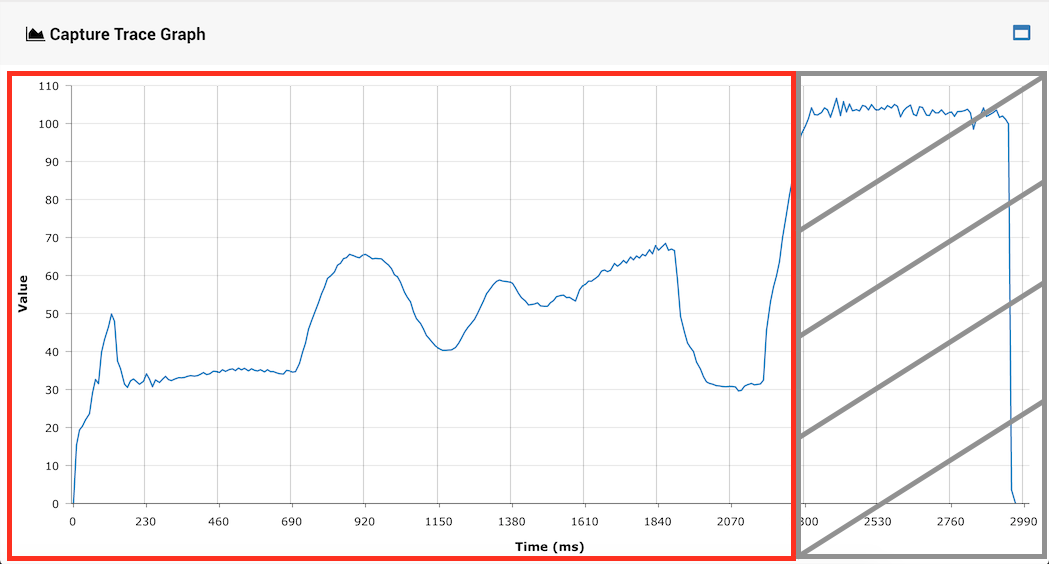
The trace can be divided into two parts, shown by the red box and grey box.
The red box shows the part of the trace where where the switch assembly (slide, clamps etc.) is in motion. The grey box shows where the movement has finished. This final region is not often relevant when diagnosing abnormal points behaviour.
It is therefore excluded in many places when calculating the average pressure and peak pressure. Where this is done, the average pressure excluding the grey region and the peak pressure excluding the grey region tend to be referred to as simply the average and the peak.
This system is used in the following places:
- Points Performance Graphs on the Points Performance Report page and the Asset Health Playback page.
- Points Analysis Graphs on the Points Analysis Report page.
- Points Alarm Wizard (Automatic and Manual) sets the average and the peak split threshold values.
Electrically Actuated Points
The electric motor current trace of an electrically actuated points swing can be analysed to identify abnormal behaviour and developing faults.
A typical motor current trace is shown below:
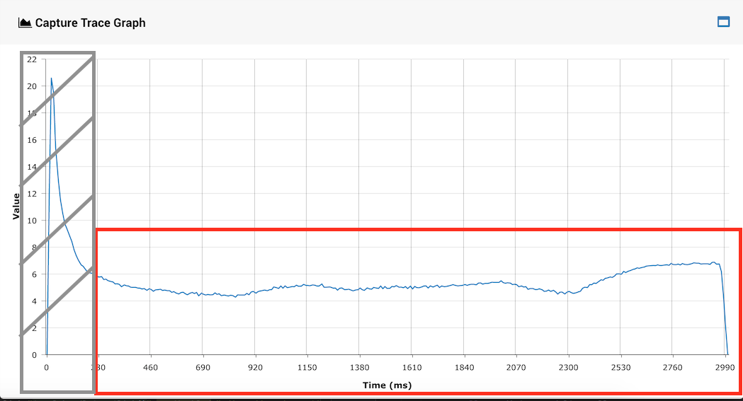
The trace can be divided into two parts, shown by the red box and grey box.
The the grey box shows the part of the trace dominated by inrush current (also known as surge current or stall current in some localities). This region is often not interesting when diagnosing incipient mechanical points failures.
It is therefore excluded in many places when calculating the average current and peak current. Where this is done, the average current excluding inrush current and the peak current excluding inrush current tend to be referred to as just the average and the peak.
This system is used in the following places:
- Points Performance Graphs on the Points Performance Report page and the Asset Health Playback page.
- Points Analysis Graphs on the Points Analysis Report page.
- Points Alarm Wizard (Automatic and Manual) sets the average and the peak split threshold values.