HXP-3 & VHLC Monitoring using the S-LX
- Mark Beeson (Deactivated)
- Mark Lock
Overview of the S-LX
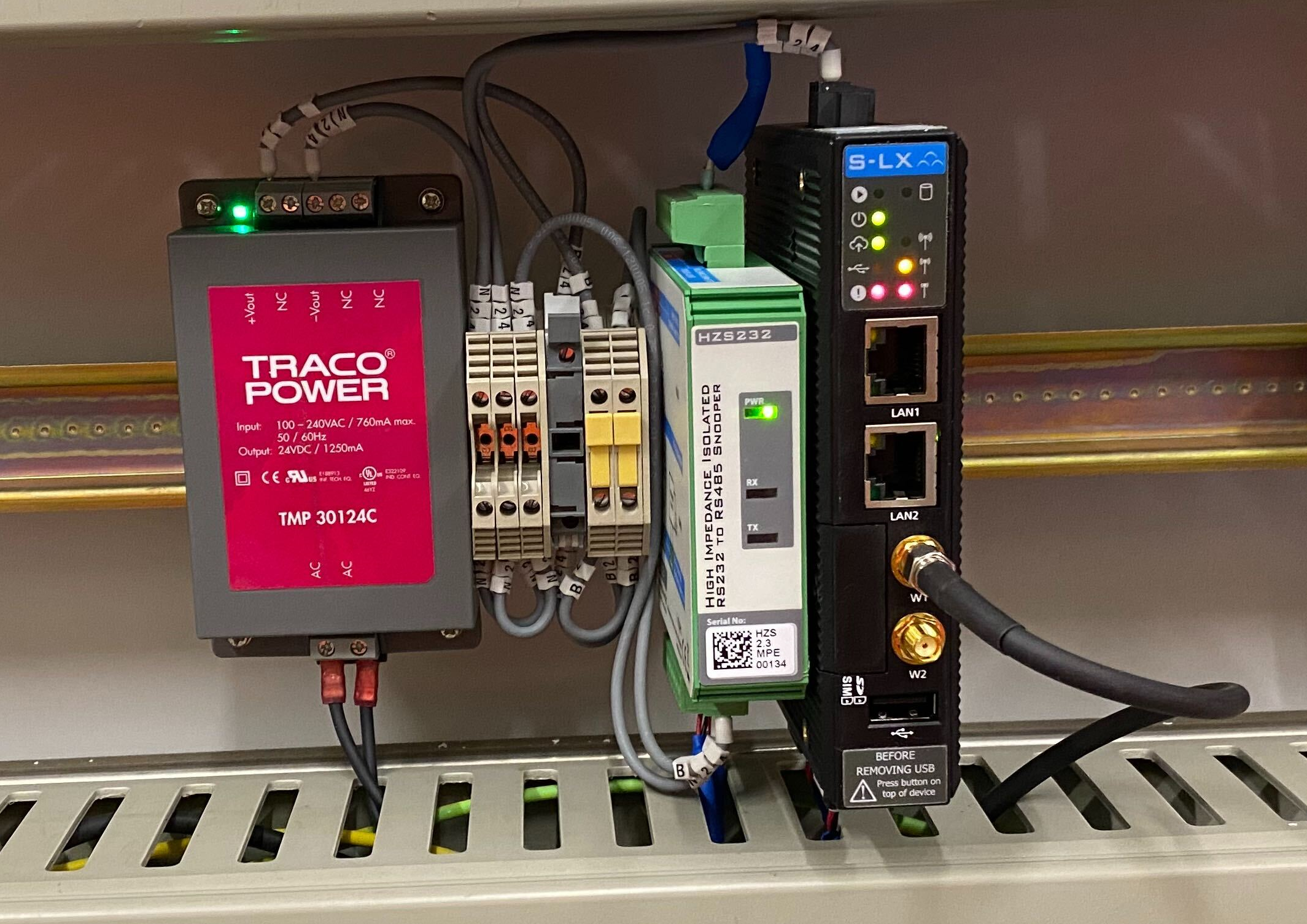
The S-LX system comprises of 3 main components mounted on standard DIN rail.
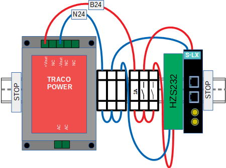
Power supply
The system is supplied through a product-approved isolated BX110 (or domestic mains) to B24 power supply. A single power supply will power 2 x S-LX computing modules and 4 x HZS232 port sniffers inclusive.
Industrial Computer (The S-LX)
The "brains" of the system is an industrial computer running application specific software.
- 2 x Serial Ports (RS232 or RS485)
- 2 x Ethernet ports for data transmission, or local master / slave networks.
- 1 x 4G Modem for onward data transmission
It receives data on its two serial ports, processes this data and forwards the processed data to the Centrix platform
In master/slave installations, only one S-LX device requires a modem, other devices can be networked together.
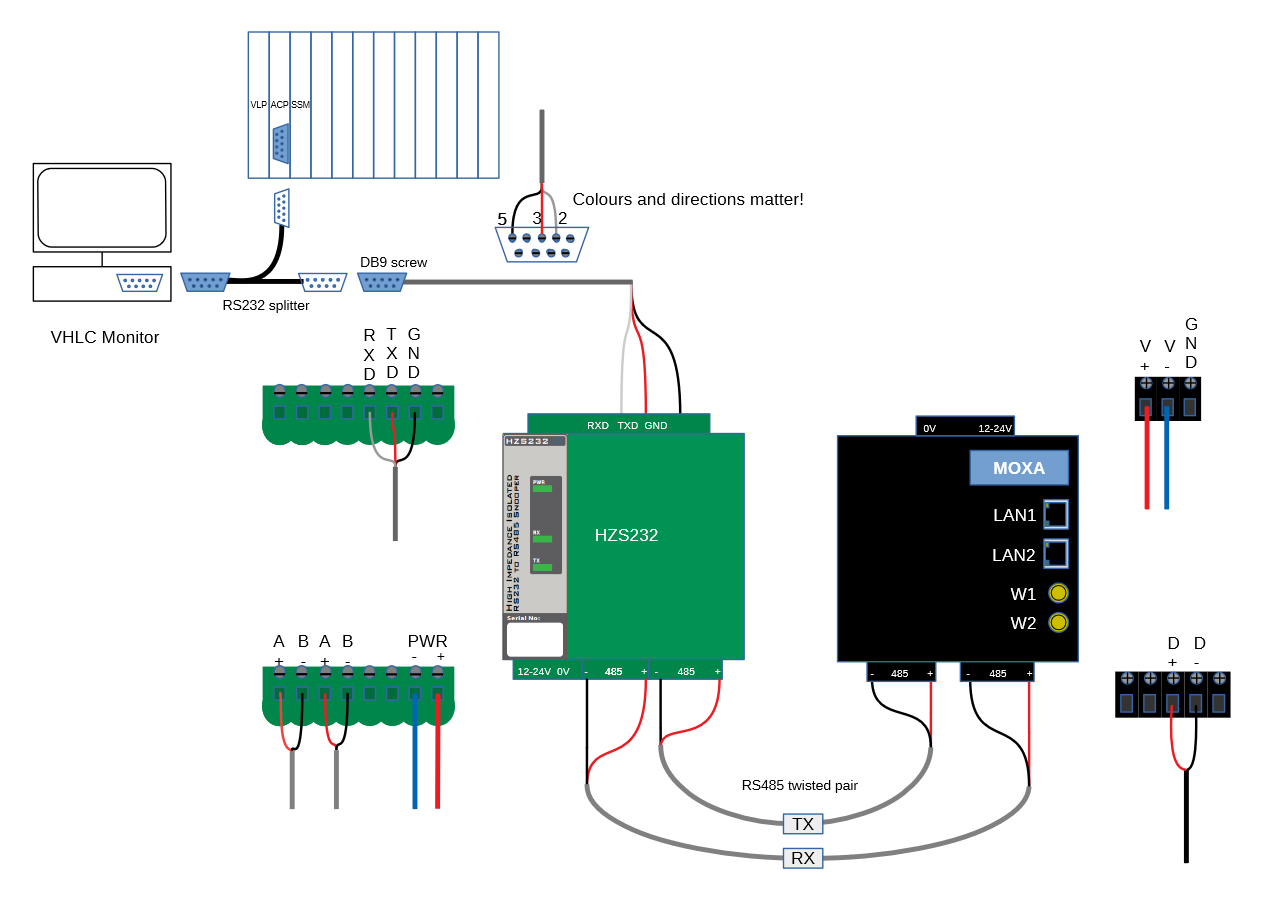
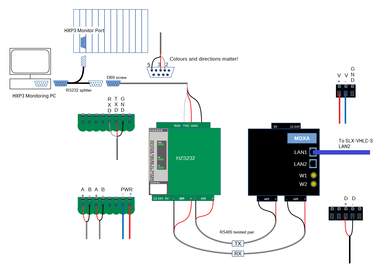
High-Impedance Serial Port Sniffer (The HZS232)
- The HZS232 "taps into" RS232 serial lines using an application specific cable set
- The device presents a high-impedance to monitored serial lines, and a fail-safe design, meaning it will not adversely affect the operation of the monitored serial link.
- The device also "isolates" the signal. It can be thought of a as a "data diode". It is not electrically possible for the S-LX computer to interfere with the data on the monitored serial link.
VHLC
How is it installed?
When utilised to monitor a VHLC level crossing, the condition monitoring data-feed between the VHLC rack and the in-situ monitoring PC is intercepted.
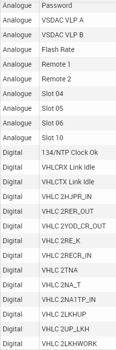
What data is available?
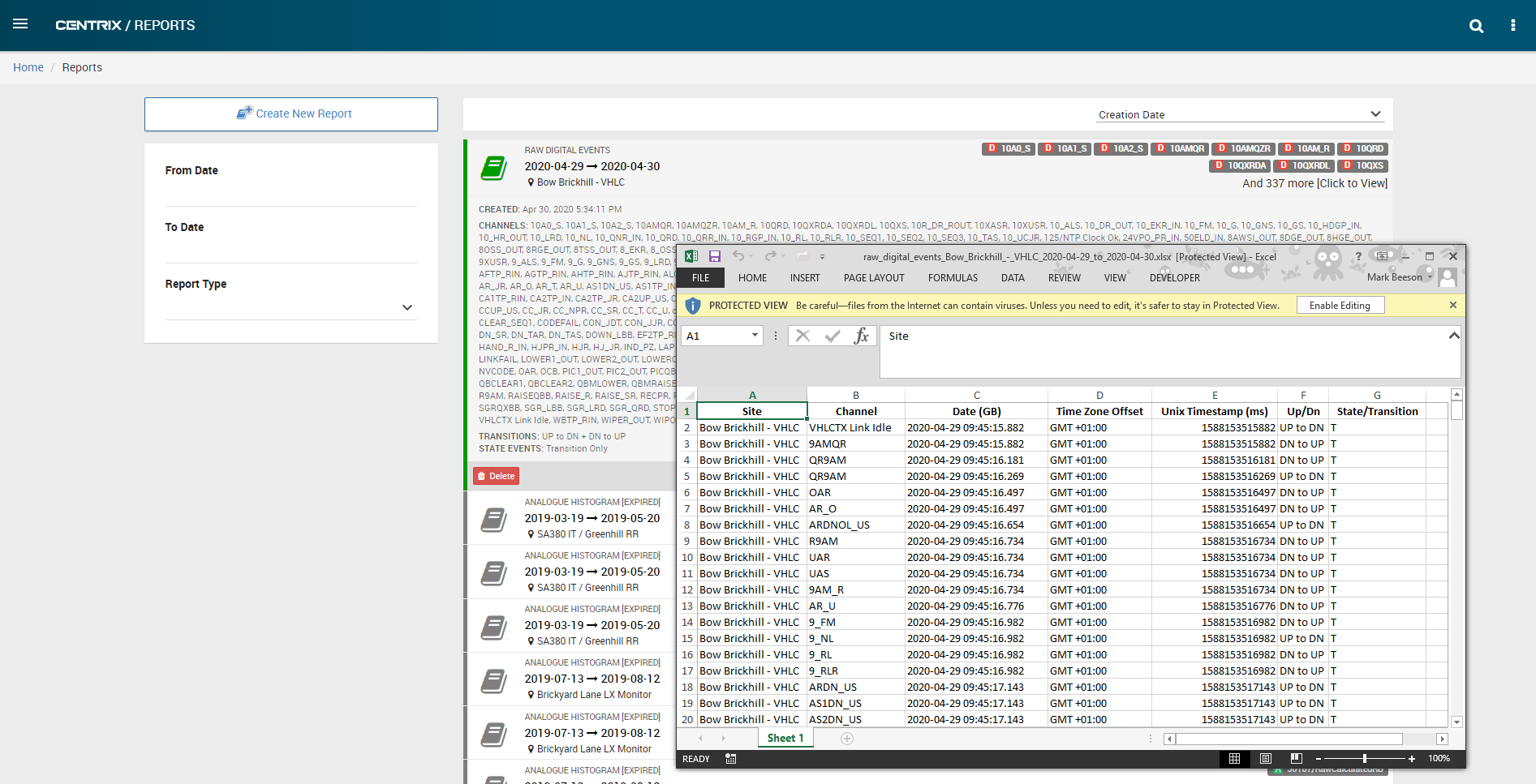
All the analogue and digital data made available on the link between monitoring PC and VHLC. A snapshot of some of the available channels is shown below. A typical VHLC may advertise over 500 digital channels and a handful of analogue channels.
The S-LX requires no channel configuration. Channels are created on-the-fly as they are observed on the data link.
How is the data is presented?
There are 4 primary means of obtaining value from the data.
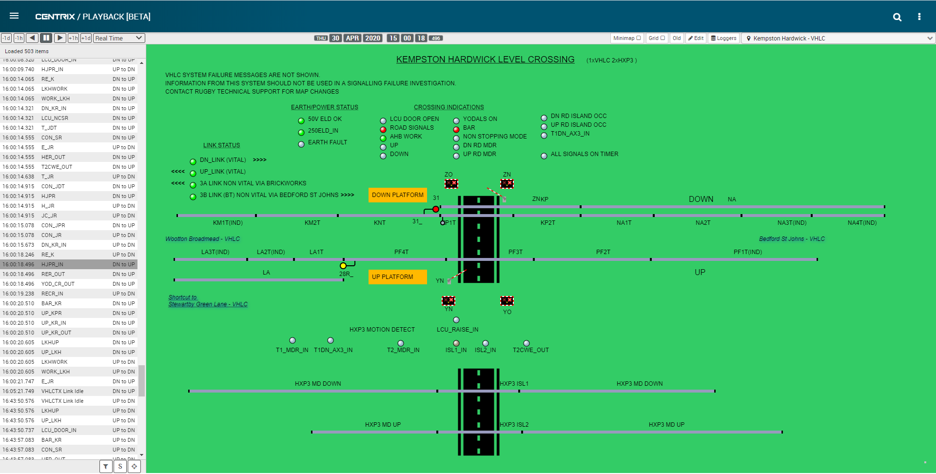
Replay
Observe the historical and live state of the crossing.
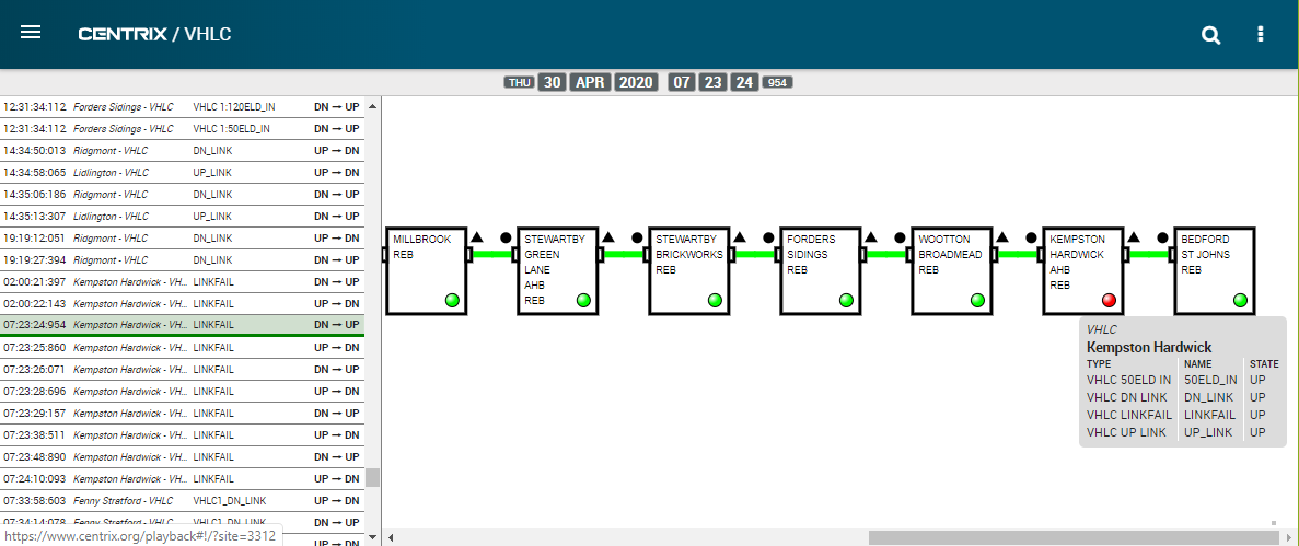
Dashboard
Observe the over-arching health status historically and in real-time of the whole line.
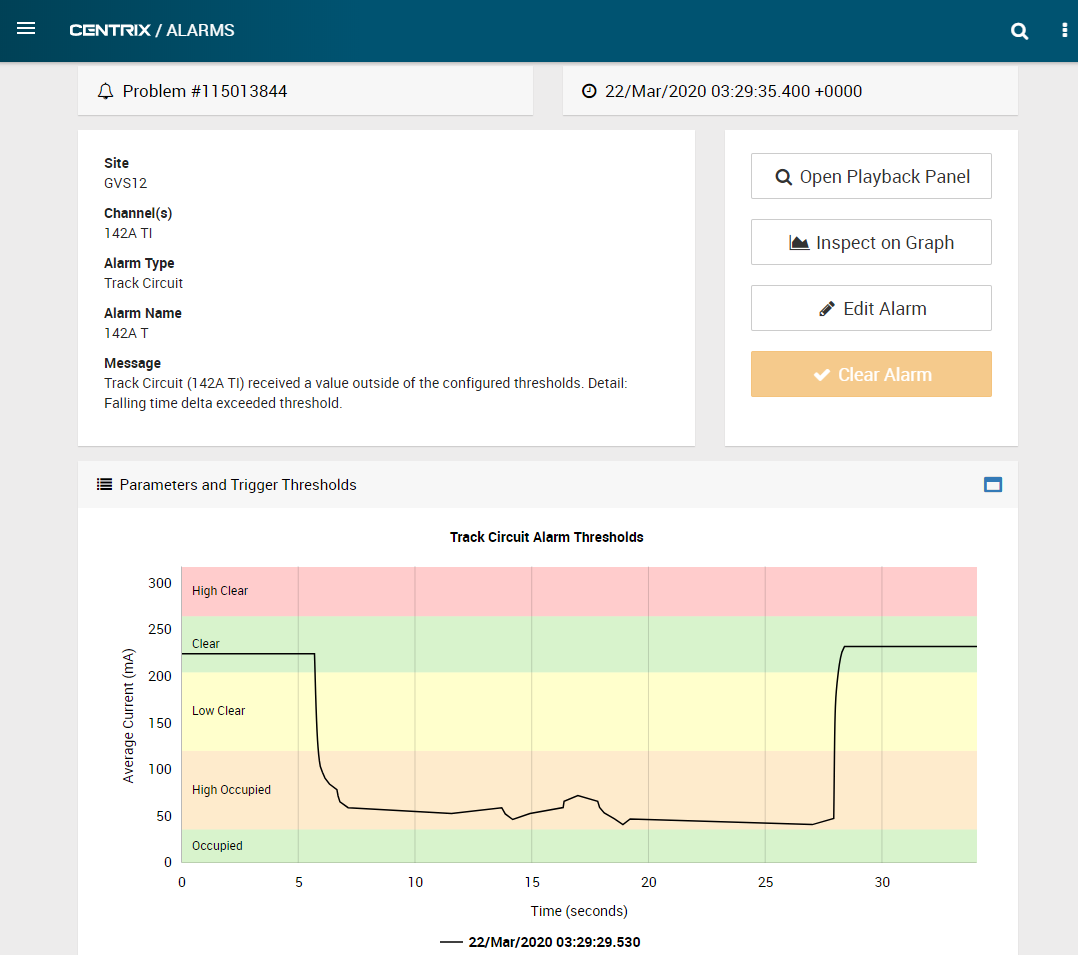
Alarms
As with traditional event monitoring, alarms may created upon the transition of any digital channel, or threshold breach of any analogue channel.
Reports
Download event data for further analysis.
HXP-3
How it is connected?
hen utilised to monitor a HXP-3 track circuit, the condition monitoring data-feed between the HXP-3 rack and the in-situ monitoring PC is intercepted. If an existing S-LX device is in-situ monitoring the VHLC crossing, then both S-LX devices may share a power supply, and the HXP-3 S-LX device does not require a modem. It can be networked to the VHLC S-LX device.
What data is available?
There are 3 sets of data available on one HXP-3 controller for each of two tracks. The values are:
|
Receive level, and received phase is available as a real-time data stream for both tracks.
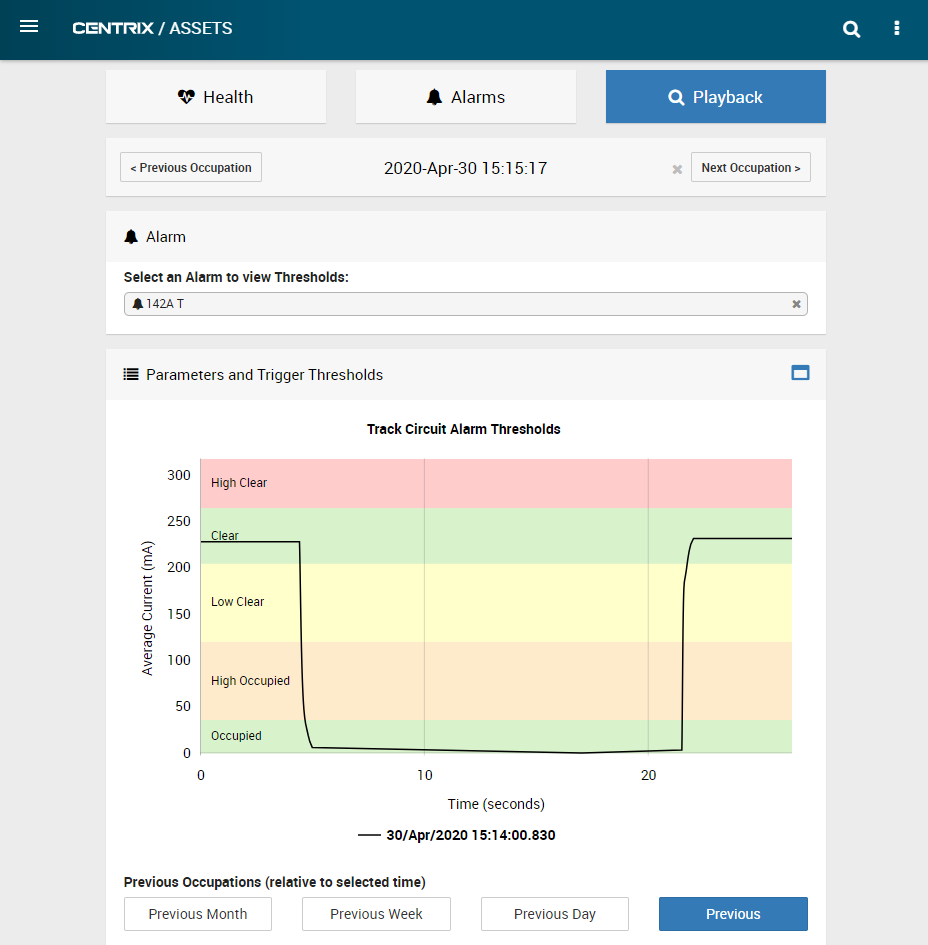
Real-world sample data can be seen on the graph below.
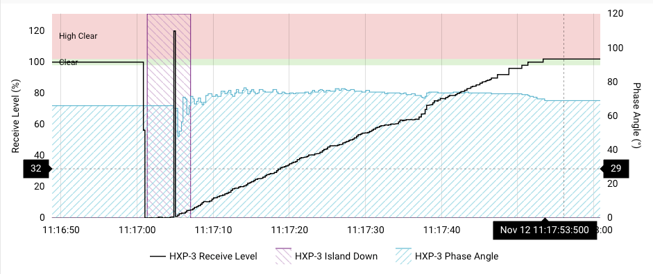
- The data is known to be untidy (the glitchy section shortly before the track clears) at the point where the train is "on-top-of" the predictor.
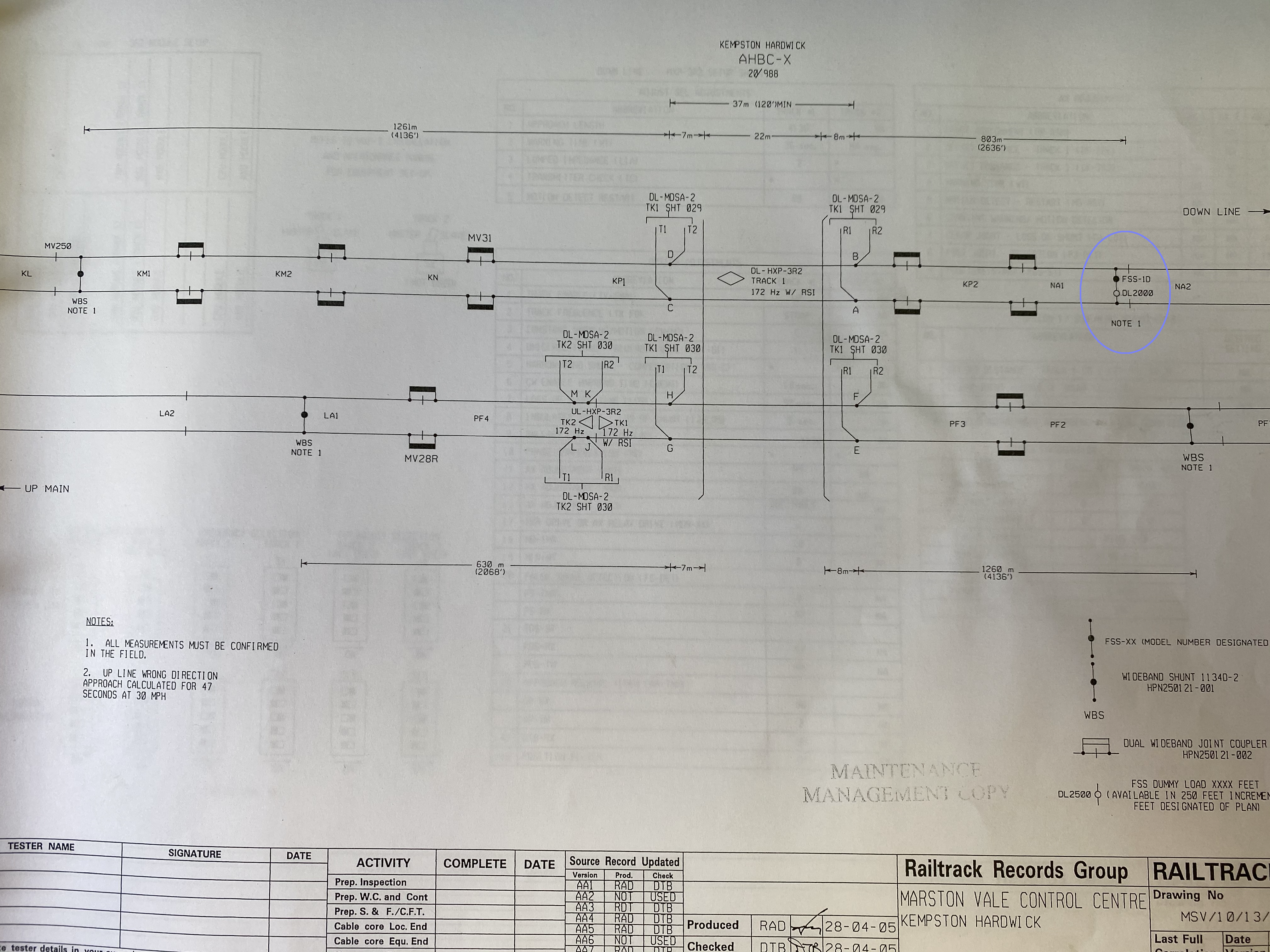
- The vertical section in the trace during clearance is due to the line section being artificially shorted with a block joint (upper track, see blue ring in diagram). Track diagram:
How is he data is presented?
This is entirely up to the customer. With no HXP-3 installs presently live, the opportunity exists to work with Mpec to develop a data visualisation and alarm strategy within Centrix that suits the needs of your daily operations.
Data from one of our existing track-circuit assets is included, but simply for reference.