Overview
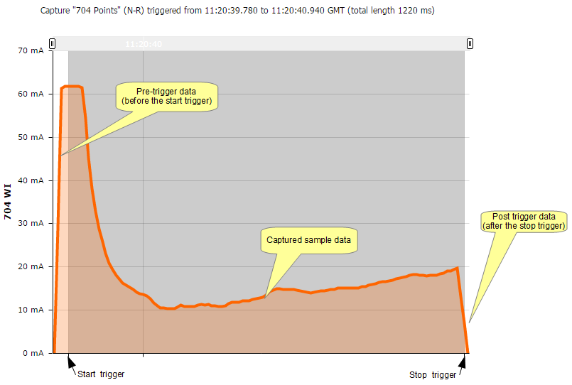
Switches can be monitored on the SA380 TX using digital inputs and analogue channels. With the SA380 TX and SA380 TX-L, this is done using the "trigger capture" mechanism. This data capture method can be applied to any data collection which starts from a known event, such as a relay picking, or a current measurement rising above a pre-determined threshold. The idea behind the trigger capture is to allow a generic configuration for any type of asset where analogue data needs to be captured at maximum sample rate. To this end, the mechanism is open to may uses other than switch monitoring. The general trigger capture consists of two triggers (start and stop) and three data capture phases (pre, during and post), which the following points trace can illustrate:
Common configuration overview
There are several common combinations of switches that are configured. The following examples illustrate these:
- Single PCM 30 (bi dirertional CT) (analogue start & stop triggers) (Electrical Machines, e.g. M63, HW2000)
- Single PCM 20 (Command relays - NWR, NWN) (digital start, analogue end) (Clamplocks, electrical or hydraulic)
- Single PCM 20 (Detection relays - NKR, RKR, digital start, digital end) (Clamplocks, electrical or hydraulic)
- Two PCM 20 - (current triggered, note: channel mapping) (electrical machines)
- Single PCM 20 - Valve CTs, CT on N-R and R-N valve (hydraulic machines)
For a switch, there are generally two transitions which should be recorded, N-R and R-N. The SA380 TX allows grouping of capture events
SA380 TX-L Logger Configuration
The logger is extremely flexible in its configuration and the type of asset that can be monitored, the following is a set of screenshots leading through the setup.
Entering capture configuration
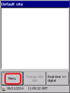
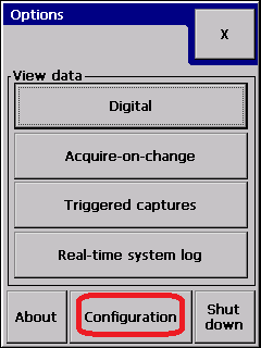
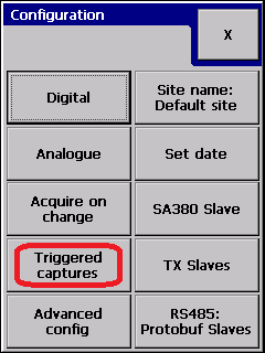
Enter the Trigger capture setup menu:
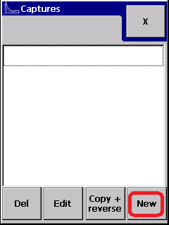
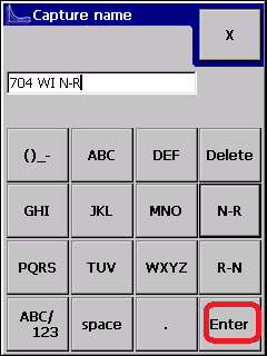
Create a new capture
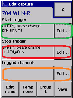
You will now be presented with the following display:
The three highlighted areas are for configuring the start trigger, the stop trigger and the analogue channels to be logged. Selecting "edit" on the right will allowing editing of each one.
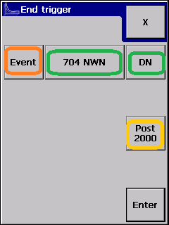
Configuring a digital trigger (start & stop)
note: The event button will allow you to configure an analogue start or stop trigger.
In the example above, the "704 NWR" and "704 NWN" relays have been selected as the trigger start and end events.
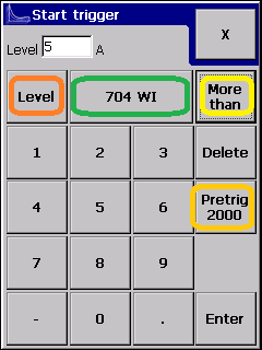
Configuring an analogue trigger (start & stop)
- the type of trigger is selected by pressing "level" or "event" (in orange).
- The channel to trigger from and the trigger type is shown (in green).
- For analogue channels, the trigger threshold is set (pale green) and the trace direction (yellow).
- The "Pretrig" value is the time period (measured in milliseconds) specifying the pre-trigger time period.
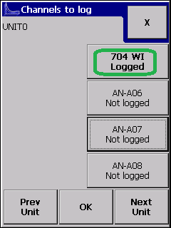
Selecting the analogue channel to collect
The analogue channel to record is selected using the following display:
The SA380 TX is capable of logging up to three analogue channels simultaneously in a capture if required. This could be used to capture motor current and hydraulic pressure simultaneously for example. Note: Centrix supports this, it is not supported by Network Rail's II platform for example.
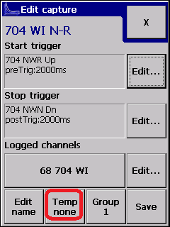
Temperature Recording
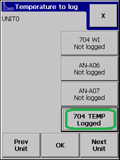
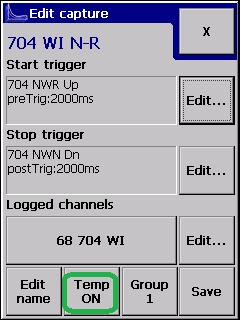
An additional reading can be made at the start of the capture (as the start trigger fires) which is reported to the central server as the temperature at the time of the capture. Only one such channel can be recorded. This is set up as illustrated below:
Related articles
