Switches can be monitored on the SA380 TX using digital inputs and analogue channels. With the SA380 TX and SA380 TX-L, this is done using the "trigger capture" mechanism. This data capture method can be applied to any data collection which starts from a known event, such as a relay picking, or a current measurement rising above a pre-determined threshold.
The logger is extremely flexible in its configuration and the type of asset that can be monitored, so the following is a set of examples showing how the system can be setup.
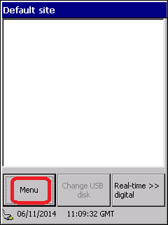
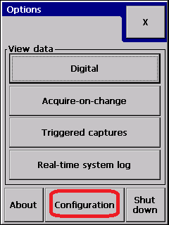
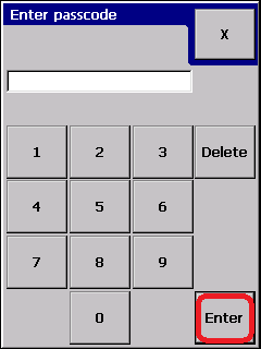
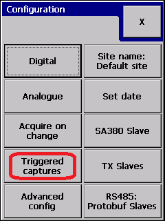
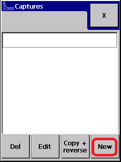
- Enter the Trigger capture setup menu: {1,2,3,4}
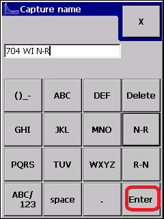
- To create a new trigger capture, choose "New", and select a suitable name, for example, "704 WI N-R" {5,6}
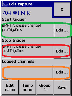
- You will now be presented with the following display:
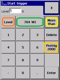
The three highlighted areas are for configuring the start trigger, the stop trigger and the analogue channels to be logged. - The start trigger should be configured according to the type of installation, and can be either a digital event (e.g. a command relay such as NWR picking) or an analogue event (e.g. motor current in 704 WI rises above 5A):
- the type of trigger is selected by pressing "level" or "event" (in orange).
- The channel to trigger from and the trigger type is shown (in green).
- For analogue channels, the trigger threshold is set (pale green)
There are several common combinations of switches that are configured. The following examples illustrate these:
Single PCM 30 (bi dirertional CT) (analogue start & stop triggers) (Electrical Machines, e.g. M63, HW2000)
Single PCM 20 (Command relays - NWR, NWN) (dig start, analogue end) (Clamplocks, electrical or hydraulic)
Single PCM 20 (Detection relays - NKR, RKR, dig start, dig end) (Clamplocks, electrical or hydraulic)
Two PCM 20 - (current triggered, note: channel mapping) (electrical machines)
Single PCM 20 - Valve CTs, CT on N-R and R-N valve (hydraulic machines)
Related articles
