| No. | Name | Description |
|---|
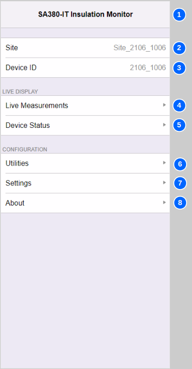
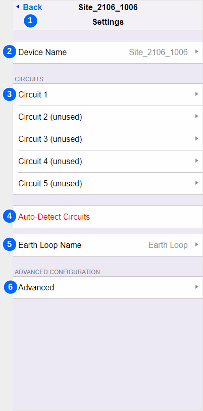
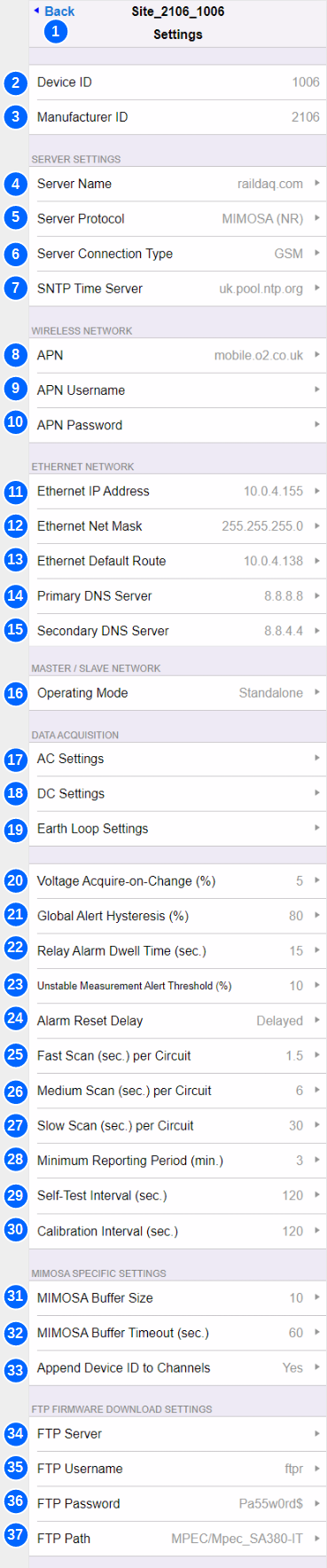
| 1 | Back | Navigates back to the Settings menu |
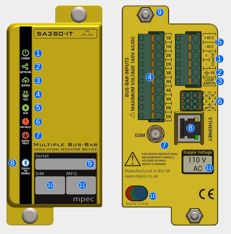
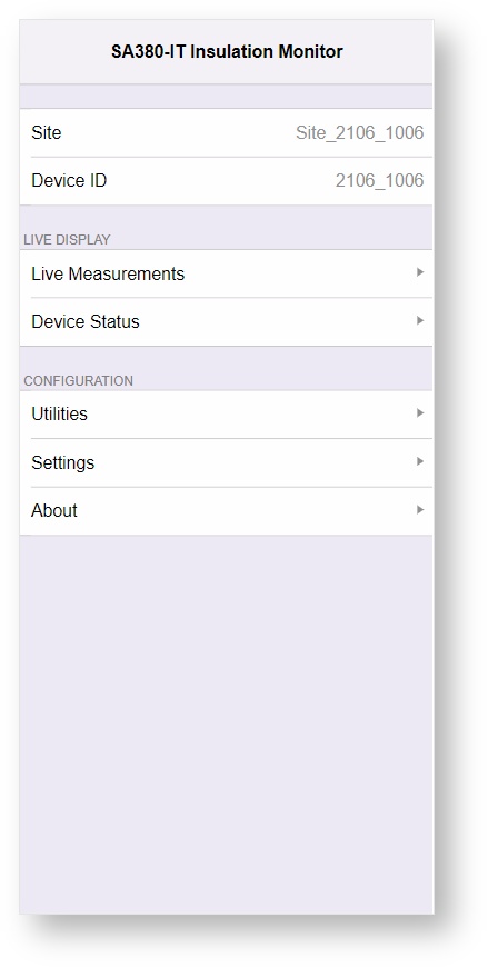
| 2 | Device ID | Set to the device serial number. This is for information only. It cannot be changed. |
| 3 | Manufacturer ID | Mpec's unique SA380-IT manufacturer ID used by the Network Rail MIMOSA protocol only. This is for information only. It cannot be changed. |
| 4 | Server Name | The hostname or IP address of the Enterprise Asset Management system you wish to connect to.
| Tip |
|---|
Default Server: raildaq.com The default server is a public server managed by Mpec. It is not intended for use with "live" deployed SA380-IT devices.
The default "raildaq.com" server provides a place for orphaned SA380-IT devices that have lost their configration to connect to. This allows Mpec to support such devices. |
|
| 5 | Server Protocol | See Data Acquisition section for more detail. | MIMOSA (NR) | Force use of Network Rail MIMOSA protocol and acquisition rules. |
|---|
| RailDAQ (Mpec) | Force use if Mpec RailDAQ protocol and acquisition rules. |
|---|
Automatic | Use the most appropriate protocol and acquisition rules for the server to which you are connected. |
|---|
|
| 6 | Server Connection Type | How to attempt data connection to the server system: | Any | Attempt connection on both GSM and Ethernet interfaces. Robust but can extend reconnection times. |
|---|
| GSM | Exclusive use of the GSM radio. |
|---|
| Ethernet | Exclusive use of the Ethernet port |
|---|
|
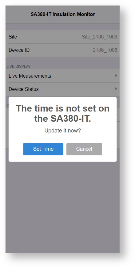
| 7 | SNTP Time Server | The name of a viable Simple-Network-Time-Protocol server. The SA380-IT will attempt to reach this server in order to set the time on the device at boot, and then once every hour. | Tip |
|---|
If connected to a MIMOSA server, you may find that the SNTP time server field has been overwritten at the request of the MIMOSA server. This is because MIMOSA servers instruct which time server the field device is to use. |
| Tip |
|---|
If connected to a RailDAQ server, the SNTP time service is not strictly required, and the field may be left blank. |
| Tip |
|---|
The default SNTP time server is resolvable on the public Internet. LAN / APN firewalls may prevent this being resolvable. |
|
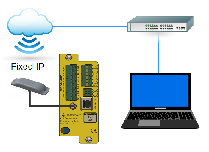
| 8 | APN | Access-Point-Name. The APN is the name of the gateway between the GSM modem and a computer network. The APN is provided by your SIM provider and dictates which network you connect to. | Tip |
|---|
Common APNs: | mobile.o2.co.uk | | The O2 network APN for connection to the public Internet | | ii-static.corp.ukrail.net | | The Network Rail private LAN connection over the O2 celluar network. The public Internet is not accessable. |
|
| Tip |
|---|
The default APN allows connection to the public Internet on the O2 celluar network. The default APN allows orphaned SA380-IT devices that have lost their configration to connect back to Mpec. This allows Mpec to support such devices. |
|
| 9 | APN Username | Some APNs require a valid username in order to permit connection to a data network. The APN username will be provided by your SIM provider. |
| 10 | APN Password | Some APNs require a valid password in order to permit connection to a data network. The APN password will be provided by your SIM provider. |
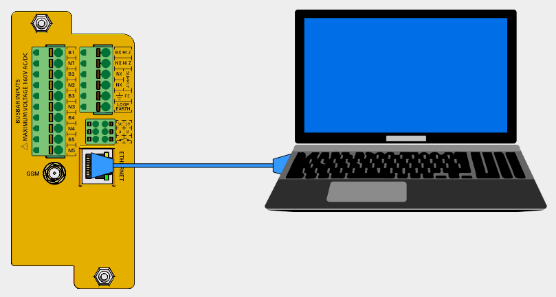
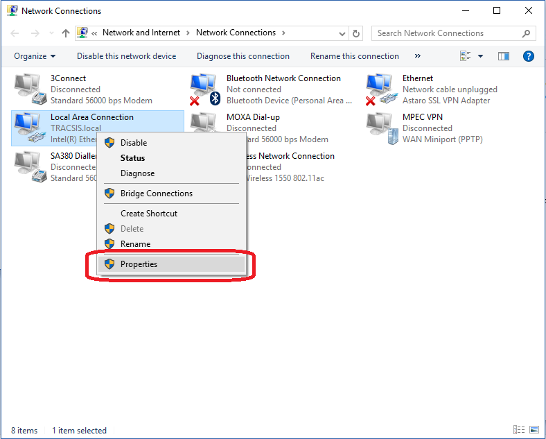
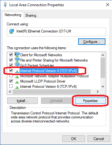
| 11 | Ethernet IP Address | The IP address of the SA380-IT on the Ethernet interface. | Tip |
|---|
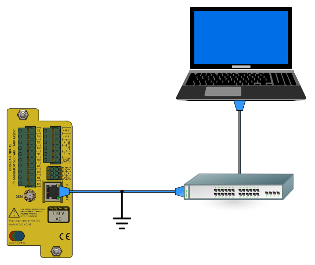
The IP address must be compatible with your local network settings, including: - point-to-point connection to a laptop
- connection to a corporate LAN
The SA380-IT does not support DHCP. IP settings must be configured manually. |
| Tip |
|---|
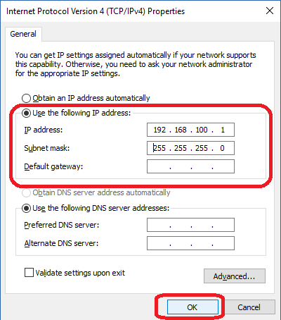
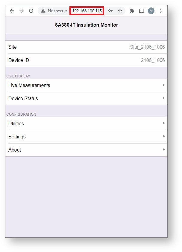
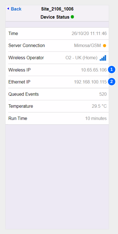
The default IP address of the device upon shipment is: 192.168.100.115 |
|
| 12 | Ethernet Net Mask | Ethernet Subnet Mask: Used to define the network subnet of the LAN to which the SA380-IT is connected. | Tip |
|---|
The subnet mask must be compatible with your local network settings, including: - point-to-point connection to a laptop
- connection to a corporate LAN
The SA380-IT does not support DHCP. IP settings must be configured manually. |
| Tip |
|---|
The default subnet mask of the device upon shipment is: 255.255.255.0 |
|
| 13 | Ethernet Default Route | Used to define the default network gateway (route) between the SA380-IT subnet and the wider LAN / Internet. | Tip |
|---|
The defualt route must be compatible with your LAN network settings to enable the SA380-IT to reach your Enterprise Server. The SA380-IT does not support DHCP. IP settings must be configured manually. |
| Tip |
|---|
The default route of the device upon shipment is: 192.168.100.1 |
|
| 14 | Primary DNS Server | Primary Domain Name Server. 1st Choice name server to use to resolve SNTP and Server hostnames into IP addresses. | Tip |
|---|
The domian name server must be compatible with your LAN network settings to enable the SA380-IT to reach your Enterprise Server. The SA380-IT does not support DHCP. IP settings must be configured manually. |
| Tip |
|---|
The default primary DNS server will be resolvable when connected to the public Internet. |
|
| 15 | Secondary DNS Server | Secondary Domain Name Server. 2nd Choice name server to use to resolve SNTP and Server hostnames into IP addresses. | Tip |
|---|
The domian name server must be compatible with your LAN network settings to enable the SA380-IT to reach your Enterprise Server. The SA380-IT does not support DHCP. IP settings must be configured manually. |
| Tip |
|---|
The default secondary DNS server will be resolvable when connected to the public Internet. |
|
| 16 | Operating Mode |
| Standalone | Act as an independent device, sending all readings direct to an Enterprise Server system. |
|---|
| Slave | Synchronises and sends all measurement data over RS485 to a master Mpec SA380TX device. Does not send data to an Enterprise Server system. SLAVE MODE IS NOT PRESENTLY SUPPORTED. |
|---|
|
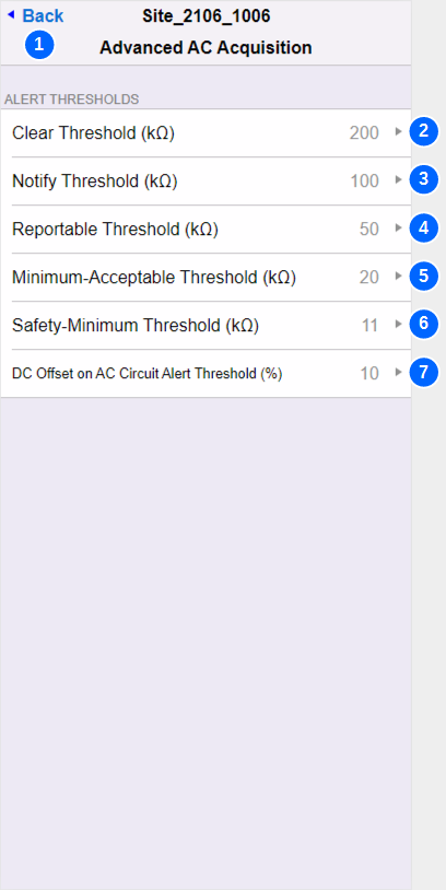
| 17 | AC Settings | Opens a menu that governs advanced setting regarding AC circuit data acquisition. |
| 18 | DC Settings | Opens a menu that governs advanced setting regarding DC circuit data acquisition. |
| 19 | Earth Loop Settings | Opens a menu that governs advanced setting regarding Earth Loop data acquisition. |
| 20 | Voltage Acquire-on-Change (%) | Governs the sensistivity of voltage data acquisition on all circuits. A new sample will be acquired whenever the voltage on a given circuit is observed to have changed by more than n% of it's previous reading. | Tip |
|---|
At low circuit voltages, acquisition is limited to changes no smaller than 0.1 V to prevent high data volumes. |
|
| 21 | Global Alert Hysteresis | Governs a hysteresis window for Earth-Loop out-of-tolerance state. For instance, if the earth loop out-of-tolerance level is set to 1,000 Ω and hysteresis is to set to 10%, then an out-of-tolerance earth loop reading must return to 900 Ω or less before the alert condition may clear. Alert clearance is sill subject to the alarm reset conditions also being satisfied.
Network Rail MIMOSA mode only Governs a hysteresis window for DC Offset on AC Circuit Threshold. For instance, if DC Offset on AC Circuit Threshold is set to 11% and hysteresis is to set to 10%, then the level of DC offset on an AC circuit must return to 9.9% of the test-pulse signal level, or less before the alert condition may clear. Alert clearance is sill subject to the alarm reset conditions also being satisfied. |
| 22 | Relay Alarm Dwell Time (Sec.) | Governs the minimum operation time of the volt-free contact output. A minimum operation time is specified to prevent: - the relay output "chattering" in the event of a a transient fault
- short duration transient faults being "missed" by external equipment that is slow to respond.
|
| 23 | Unstable Measurement Alert Threshold (%) | Network Rail MIMOSA mode only The SA380-IT tracks the percentage of failed measurements over a given reporting period on each circuit using Mpec's propriatary transient detection technology. If the percentage of failed measurements in a reporting period exceeds this thresold, then the UNSTABLE MEASUREMENT status-bit is set for the effected circuit and sent to the server. |
| 24 | Alarm Reset Delay | Governs the recovery process for non-critical device interlocks (alarm conditions) Measurement of input circuits will recommence under the following circumstance: | Immediate | Restarts as soon as the fault condition has been proven to be clear. NOT PRESENTLY SUPPORTED |
|---|
| Delayed | Restarts if the fault condition has been proven to be continously clear for the device reporting period |
|---|
| Manual | Measurement will only restart once a manual Reset Device Interlocks command is issued |
|---|
See Principals of Operation for a full discription of non-critical device interlocks |
| 25 | Fast Scan (Sec. per Circuit) | This setting is obsolete and scheduled for removal. The setting does not govern anything. |
| 26 | Medium Scan (Sec. per Circuit) | Network Rail MIMOSA mode only If measurement time of an individual circuit exceeds the medium scan setting, the Long Scan Mode status bit is set for the effected circuit and sent to the server. |
| 27 | Slow Scan (Sec. per Circuit) | Network Rail MIMOSA mode only If measurement time of an individual circuit exceeds the long scan setting, the Time Out status bit is set for the effected circuit and sent to the server. |
| 28 | Mimimum Reporting Period (Mins.) | |
| 29 | Self-Test Interval (secs.) | The number of seconds between self-test cycles. | Note |
|---|
Sets the maxium period a fault can exist prior to detection. |
Increased frequency has a marginal impact on device responsiveness. |
| 30 | Calibration Interval (secs.) | The number of seconds between calibration cycles. Increased frequency has a marginal impact on device responsiveness. Reduced frequency has a marginal impact on accuracy. |
| 31 | MIMOSA Buffer Size | Network Rail MIMOSA mode only Controls how many samples to buffer before constructing a MIMOSA message. | Tip |
|---|
Waiting for messages to buffer increases coms efficiency, but incurs a delay in sending data to the server. Buffer size controls how efficiently the data packets can be assembled. |
| Tip |
|---|
It is recomended to not exceed a setting of 20 samples, and this is the maximum number of samples that the SA380-IT can combine into a single MIMOSA message. |
|
| 32 | MIMOSA Buffer Timeout (secs.) | Network Rail MIMOSA mode only Controls how long messages can wait in the messaging buffer before constructing a MIMOSA message. | Tip |
|---|
Waiting for messages to buffer increases coms efficiency, but incurs a delay in sending data to the server. Buffer timeout limits this delay. |
|
| 33 | Append Device ID to Channels | The operation of the Network Rail II/RADAR server makes it diffcult to ascertain which field device a data channel belongs to. Appending the device ID to each channe name eases idintification of data channels is this server system. | Unappended | BX110 | There will be many channels named BX110 |
|---|
| Appended | 10345:BX110 | This BX110 channel belongs to device no. 10345 |
|---|
|
| 34 | FTP Server | Network Rail MIMOSA mode only The hostname of the Network Rail II/RADAR FTP server for firmware upgrade. The SA380-IT will attempt to connect to this server upon start-up, and the between 2 AM and 4 AM UTC each day. If connection is succesful and new firmware is found, device firmware will be automatically downloaded and installed. | Tip |
|---|
Automated FTP firmware upgrade is only supported in Network Rail MIMOSA mode. No FTP upgrade attempt will be made in RailDAQ mode. |
| Tip |
|---|
Automated FTP firmware upgrade attempts can be inhibited by setting the field to be blank. |
|
| 35 | FTP Username | Network Rail MIMOSA mode only The FTP server requries a username. This is specified by the FTP server administrator. |
| 36 | FTP Password | Network Rail MIMOSA mode only The FTP server requries a password, This is specified by the FTP server administrator. |
| 37 | FTP Path | Network Rail MIMOSA mode only This specifes the "file path" on the FTP server in which to look for new SA380-IT firmware. This is specified by the FTP server administrator. |