VTi21 Global Release #109
Overview of Changes
Variant | New Version | Changed |
|---|---|---|
| Aster | 109 | Yes |
| FS2600 | 109 | Yes |
| Reed Relay | 109 | Yes |
| UM71 | 109 | Yes |
| VT1 | 109 | Yes |
New Features
HVI Track Circuit
Overview
The VTI21 can be used to monitor HVI track circuits. The VTI21 is capable of monitoring two such track circuits in parallel. This data is made available on the RS485 bus connected to a suitable MPEC master logger (typically an SA380TX). In some applications where a suitable MPEC logger is not available, the 4-20mA output may be used to provide track occupation RCM on channel 1.
The HVI (High Voltage Impulse) track circuit sends between discreet pulses at a steady rate (3-5 per second). As well as reporting the frequency of these pulses, our monitoring solution analyses each individual pulse to determine it's strength at the track circuit receiver and also that it meets a set of criteria which distinguish the signal as a HVI pulse. The strength of the pulses (our "InPulseRMSCurrent" channel) is analogous to the current in a DC track circuit, and we can therefore use a similar approach to monitoring this system as we would with a DC track circuit - we expect a "high" clear current and "low" occupied current in a healthy track circuit.
We also monitor the current seen outside of the HVI pulses, which is indicative of interference from e.g. stray traction currents, a known failure mode of HVI equipment. Our solution is also capable of detecting pulses from adjacent HVI track circuits to the one being monitored (determined by observation of pulses of opposing polarity), which would indicate IRJ failure.
Installation
To monitor two HVI track circuits, the receiver feed must be fed through the split core CT on the relevant channel.
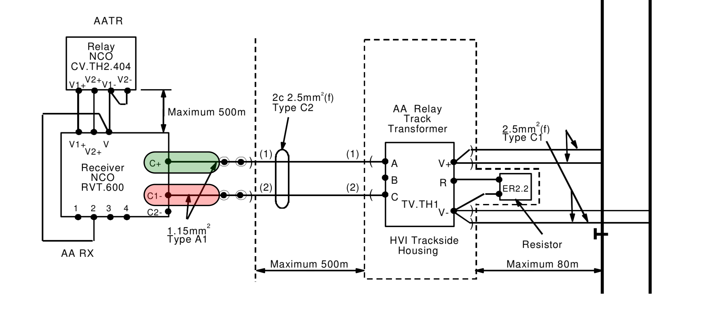
Installation of the CTs
The CT (one per track circuit) should be installed in one of the positions indicated above in red and green.
The CT can be attached in either orientation - the VTi21 can determine the polarity based on the asymmetry of the HVI waveform and correct for it.
Outputs
The following data is available from the sensor. Each pulse is captured by the VTi21 (sampled at 25KHz) and analysed to determine polarity, suitability of the waveform and the RMS current. The following values can be recorded by the data logger according to standard acquire on change rules. The 4-20mA output is only available for channel 1.
Quantity | Range | Units | 4-20mA | RS485 | |
|---|---|---|---|---|---|
| HVI Current | 0 to 1500 | RMS Current of the pulsed waveform | mA |
| |
| HVI Frequency | 0 to 5 | The frequency of pulses | Hz | ||
| Noise Current | 0 to 1500 | The RMS current observed between pulses. | mA | ||
| Pulse Conflict | Digital | Set TRUE if pulses are observed to be bleeding through from adjacent track sections | NA | ||
| Pulse Waveform | 0 to 1500 | If this channel is requested as a capture, the VTi21 will return a high-resolution waveform of the last observed pulse | mA |
*4-20 mA Signal Range: 0 to 600 mA. Available for Input Channel 1 only.
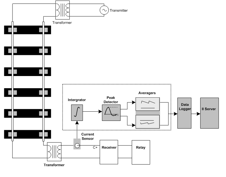
How it works
A typical HVI circuit schematic is shown below:
The HVI track circuit operates by applying a short high voltage impulse to the rails at relatively long intervals. The asymmetric operating waveform has the shape of a high peak voltage (termed the positive polarity). A proportion of this is reflected back as a reverse voltage of much lesser amplitude (termed the negative polarity).
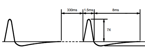
The VTI21 integrates this receiver current signal and then performs a peak detect function on both the positive and negative portions of the integrated pulse. These values are reported directly.
Bug Fixes
All variants
Increased the duration of the timeout after which the VTi21 will restart when it hasn't received any RS485 communications from its master.
This improves the reliability of master-slave networks, especially during slave firmware update on large networks.