Audio Frequency (EbiTrack 200 / TI21) Applications
Overview
The VTi21 can be used to monitor TI21 (EBITrack 200) audio frequency track circuits.
- Supports standard power Transmitter current monitoring (Part No: VTI21-TI21-TX)
- Supports low power Transmitter current monitoring (Part No: VTI21-TI21-TX-LP)
- Supports Receiver current monitoring (Part No: VTI21-TI21-RX)
Please note, that presently, this VTi21 variant only supports 4-20 mA analogue output
- Use only 1 Current Transducer per VTi21
- Ensure that the transducer is connected to VTi21 input channel 1 (CH1)
Transmitter units and receiver units require different current transducers
- Use SCT-0400-025 with standard power transmitters
- Use SCT-0400-005 with low power transmitters
- Use SCT-0400-001 with receivers
No RS485 output is supported.
RS485 output can be added in future. Please contact Mpec if this is of interest.
Installation
- The VTi21-TI21 variants are only able to monitor 1 track circuit per device.
- The current transducer must only be connected to Channel 1 of the VTi21
- VTi21 devices for monitoring EbiTrack / TI21 standard power Transmitter units must use the current transducer SCT-0400-025. (Ships with VTI21-TI21-TX)
- VTi21 devices for monitoring EbiTrack / TI21 low power Transmitter units must use the current transducer SCT-0400-005. (Ships with VTI21-TI21-TX-LP)
- VTi21 devices for monitoring EbiTrack / TI21 Receiver units must use the current transducer SCT-0400-001. (Ships with VTI21-TI21-RX)
The only difference between TX and RX models are the transducers. TX and RX VTi21 units are interchangeable if the transducer element is swapped.
To monitor track circuits, the a feed cable must be fed through the split core CT. The direction of current flow is not significant in the CTs.
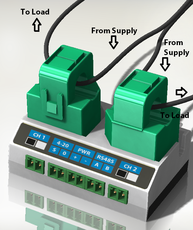
- For Transmitters: Pass one of the wires leading from either the "O/P 1" or "O/P 2" connection on the transmitter module through the current transducer.
- For Receivers: Pass one of the wires leading from either the "IP 1", "IP 2" or "IP C" connection on the receiver module through the current transducer.
Outputs
The VTi21 will automatically detect the frequency code of the track circuit to which it is connected, and then output the average of the upper and lower sideband currents observed in this frequency band.
The differing sensitivities of the current transducer used for the monitoring of EbiTrack / TI21 transmitter and receiver units mean that the output scaling will differ for the VTI21-TI21-TX and VTI21-TI21-RX variants.
| Quantity | VTI21-TI21-RX | VTI21-TI21-TX-LP | VTI21-TI21-TX |
|---|---|---|---|
| EBITrack Average Side-Band Current | 0 to 200 mA | 0 to 1 A | 0 to 5 A |
Increased Sensitivity
The VTi21-TI21-RX model is designed to output between 0 and 200 mA on the 4-20mA interface, as 200 mA is the largest "track clear" current that is normally seen in service.
The actual range of track clear currents for EbiTrack / TI21 is however quite broad. Sometimes it may be as low as 12 mA when clear. This gives very little dynamic range between clear and occupied track states, making detection of developing fault more difficult.
The improve the situation, greater sensitivity can be achieved by passing multiple-turns of wire through the current transducer.
Multiple Turns
If receiver sensitivity needs to be increased by applying multiple turns through the transducer, the 4-20 mA output will require re-scaling as follows:
| Number of Turns | VTI21-TI21-RX 4-20mA Range |
|---|---|
| 1 | 0 to 200 mA |
| 2 | 0 to 100 mA |
| 3 | 0 to 67 mA |
| 4 | 0 to 50 mA |
| 5 | 0 to 40 mA |
How Does it work?
Overview
- The VTI21-TI21 is designed to offer a simple, yet effective solution for the monitoring of both EbiTrack 200 transmitters and EbiTrack 200 receivers
- The output parameter is the equivalent of the IAVE channel found on the EbiTrack 200 digital receiver.
- The IAVE channel is the mean value of the "Upper" and "Lower" sideband currents.
- The VTi21 device is "zero-config". The VTi21 "locks-on" to the correct EbiTrack frequency and remembers that frequency.
- Differing current levels of transmitter and receiver are accommodated through the use of current transducers with differing sensitivity ranges.
- It is only possible to monitor one TX or RX per VTi21, as there is only 1 x 4-20 mA per VTi21 device.
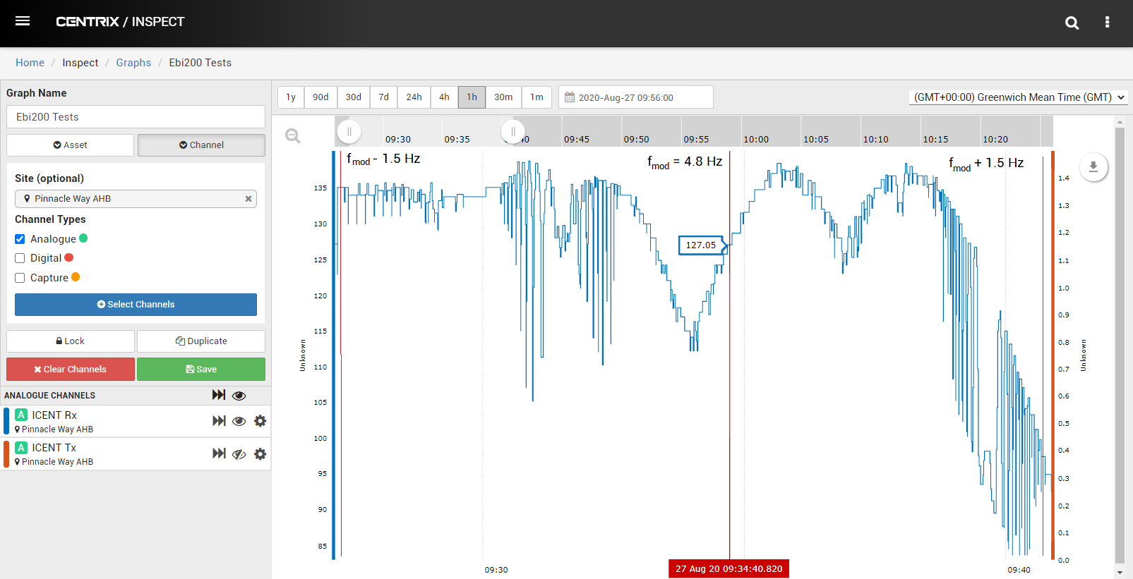
Spectrum & Frequencies
Here's an example spectra of a frequency code "D" EbiTrack 200 signal.
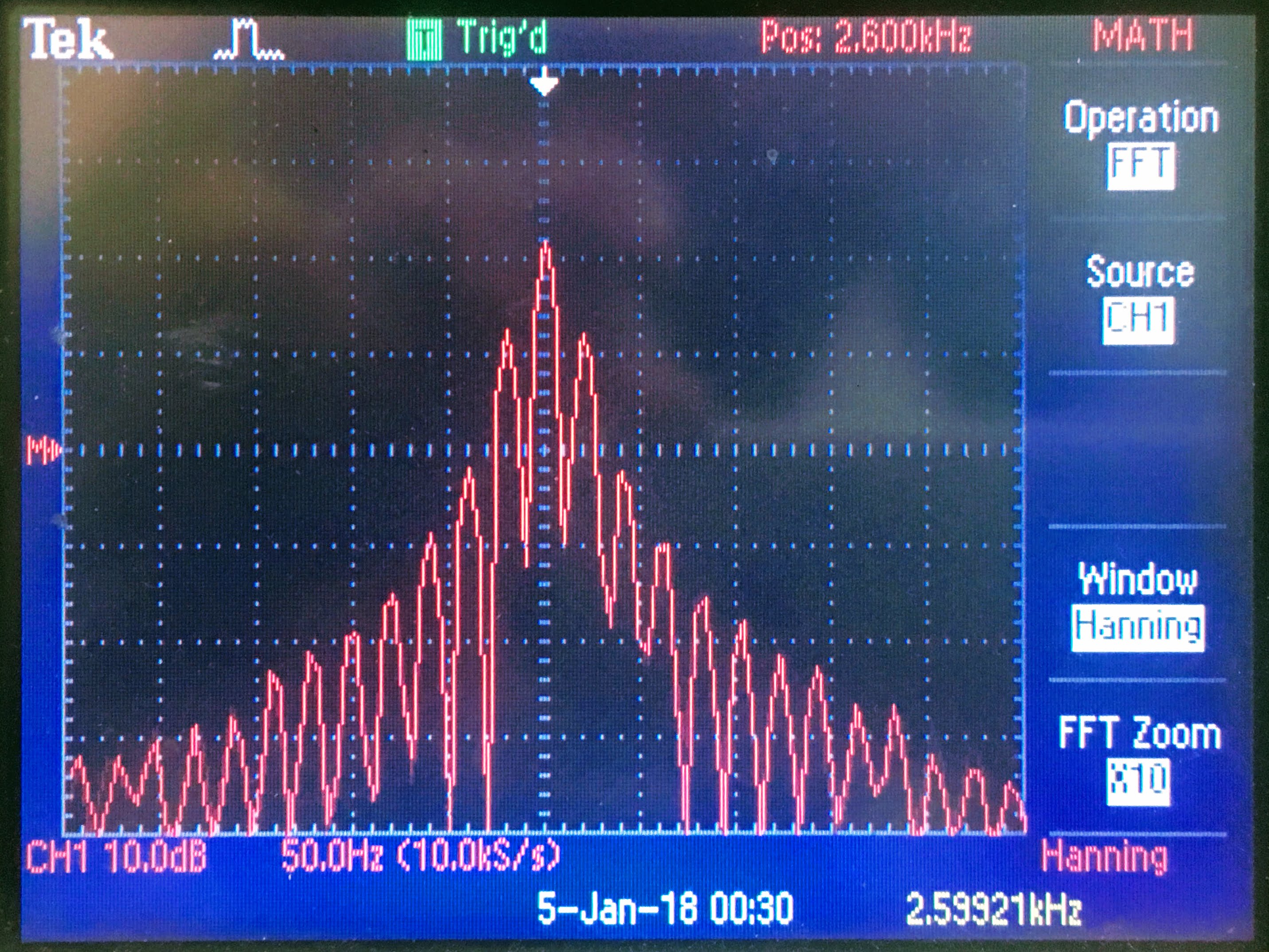
EbiTrack 200's come in 8 distinct varieties, with each of the varieties having a different centre frequency.
The different types and their frequencies are listed below:
Code | Centre Frequency (Hz) | Upper Sideband (Hz) | Lower Sideband (Hz) | Modulation Rate (Hz) |
|---|---|---|---|---|
| A | 1699 | 1682 | 1716 | 4.8 |
| B | 2296 | 2279 | 2313 | 4.8 |
| C | 1996 | 1979 | 2013 | 4.8 |
| D | 2593 | 2576 | 2610 | 4.8 |
| E | 1549 | 1532 | 1566 | 4.8 |
| F | 2146 | 2129 | 2163 | 4.8 |
| G | 1848 | 1831 | 1865 | 4.8 |
| H | 2445 | 2428 | 2462 | 4.8 |
Key:
Item | Meaining |
|---|---|
| Code | The EbiTrack 200 has 8 varieties, this letter-code (A to H) makes it easy to the reference which operating frequency you have. |
| Centre Frequency | This is the frequency equidistant between the sidebands. This frequency is not actually generated anywhere, it is an artefact created by the frequency modulation of the two sideband frequencies. The VTI21 looks for these "false" frequencies in order to detect to which of the 8 EbiTrack varieties the device is connected. |
| Upper Sideband | The transmitter generates two tones, and alternates between these tones at the "modulation rate". The higher pitched of these tones is the upper sideband. The VTi21 detects the energy present at this frequency within a very narrow band with high precision. |
| Lower Sideband | The transmitter generates two tones, and alternates between these tones at the "modulation rate". The lower pitched of these tones is the lower sideband. The VTi21 detects the energy present at this frequency within a very narrow band with high precision. |
| Modulation Rate | This governs how often the transmitter hops between emitting upper and lower sideband frequencies. |
Description of Behaviour and Outputs
Digital Filters
The VTi21 will operate a series of precision digital filters, each capable of picking out the sideband and centre-band currents of each of the EbiTrack frequency code.
- 8 x Coarse "wide-band" Filters
- 2 x Fine "narrow-band" Filters
- The Coarse filters will remain fixed in frequency and are required in order to determine the correct "lock-on" frequency. This is how the VTi21 works out which frequency code it has been installed upon.
- The fine filters are narrow-band and are centred upon the upper and lower sideband frequency of the Ebitrack variant being monitored. The centering of these filters will change dependant on the selected lock-on frequency. The fine filters are very precise, only measuring the current present with a narrow frequency bands that extends 4.25 Hz either side of the ideal sideband frequency.
- The average of the two currents observed in the upper and lower sidebands is presented on the 4-20 mA interface. It is commensurate with the IAVE parameter on the digital display of the EbiTrack 200 digital receiver.
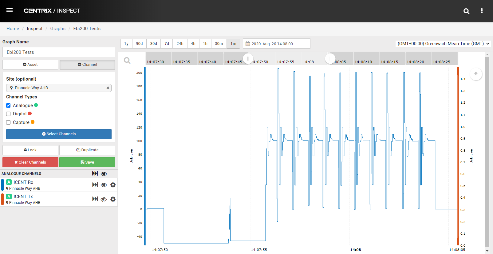
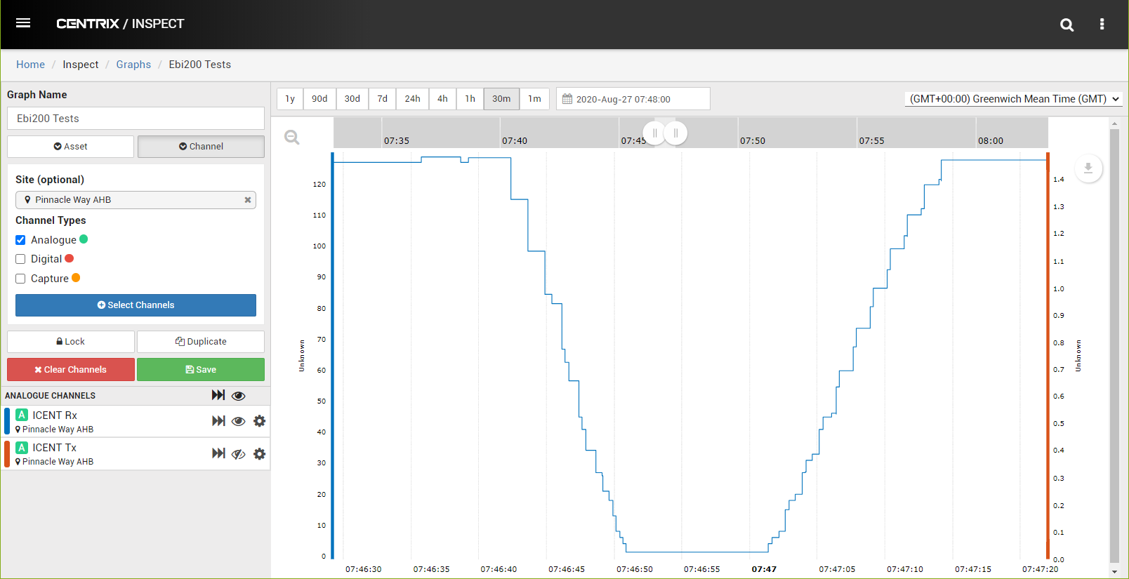
Sensor Power On
Whenever the VTi21 first powers on, the sensor undertakes a self-calibration routine to assure the accuracy of the 4-20mA output.
This will produce the cyclic waveform shown below. This is not cause for alarm. It is a normal part of the VTi21 devices operation.
Lock On behaviour
- After calibration, the VTi21 will start to inspect the frequency content of the current flow in the monitored conductor
- The VTi21 is looking for the "loudest" EbiTrack 200 / TI21 channel present (A to H)
- The VTi21 will "lock-on" to the loudest channel, so long as that channel has an IAVE output above a preselected threshold (to provide immunity to noise)
- VTI21-TI21-RX: >6 mA
- VTI21-TI21-TX-LP: >30 mA
- VTI21-TI21-TX: >150 mA
- After lock-on, the VTi21 will start to report the average side-band current of only the selected frequency channel
- The VTi21 will remember the lock-on channel until:
- The VTi21 restarts, or
- No signal greater than 6mA has been observed on the selected channel for a period of more than 2 weeks.
- In both cases, the lock-on detection process will repeat. This prevents the VTi21 from "forgetting" the lock-on channel during extended periods of track occupancy or failure.
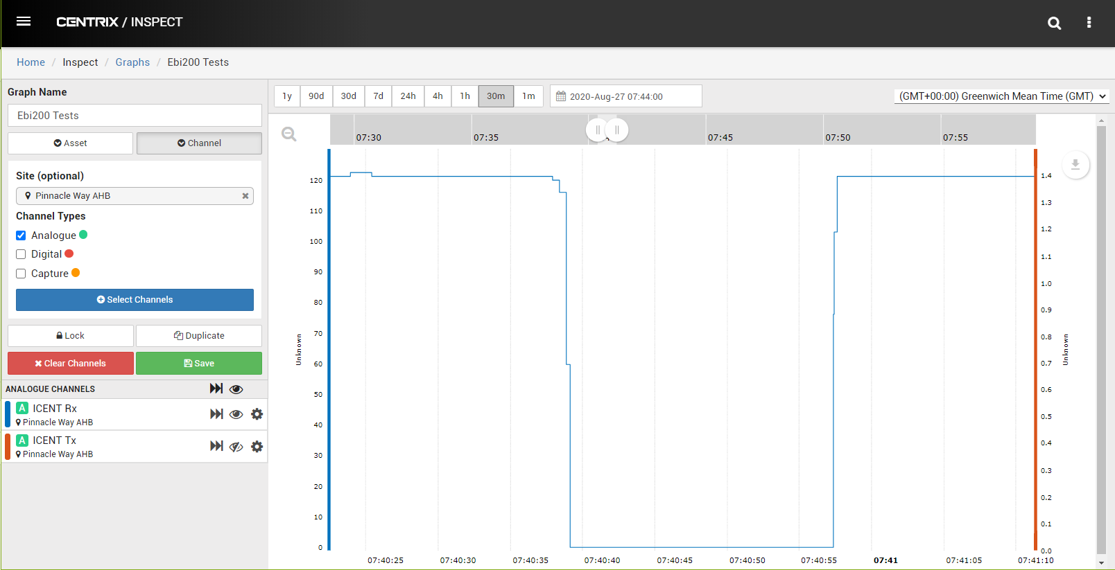
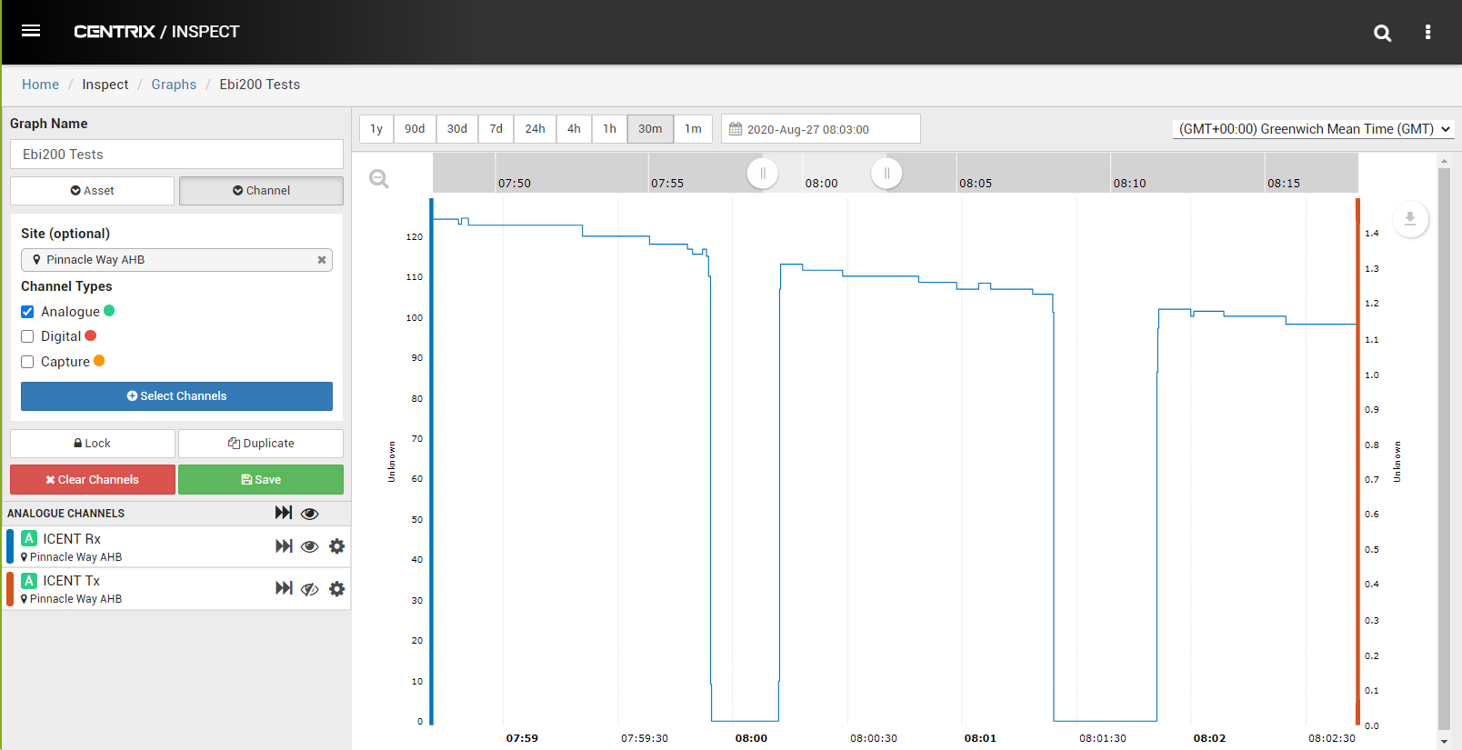
Sudden Shunt
A healthy track circuit will exhibit a steady "clear" current and an occupation current of near-zero. If a short-circuit is placed across the rails, the receiver current should drop to zero almost immediately.
When the short-circuit is removed, the steady clear current should resume, almost immediately.
This behaviour is shown in the graph below:
Train Passing Through the Tuned Zones
In a typical EbiTrack 200 / TI21 installation, the track circuits are "joint-less", there is therefore a gradual shunting and clearance characteristic curve that occurs when the train enters and departs the track section as the train passes through the tuned zones. The speed at which the track circuit transitions from fully occupied to fully clear is a direct function of the length of the tuned zone and the speed of the train.
This behaviour is shown in the graph below:
Rail-head Contamination
One of the key benefits of track circuit RCM is the ability to detect a poor shunt, before it develops into a dangerous wrong-side-failure. Effects such as railhead contamination will manifest a "bumps" in the current plot during the occupation phase.
This behaviour is shown in the graph below:

Ballast Degradation
Poor ballast conditions can cause track circuits to fail "right-side". If the "ballast resistance" becomes too low, then over time, the "clear" current can drop low enough to fail to maintain the output relay energised.
Such faults generally develop slowly, but can be accelerated by rainfall and flooding.
This behaviour is shown in the graph below:
Mistuning of Side-bands
The EbiTrack 200 / TI21 VTi21 variant is finely tuned to detect the exact sideband frequencies used by the EbiTrack 200 / TI21 system.
If these sidebands become "mistuned" the the output of the VTi21 will begin to roll-off
The graph below shows the effect of both side-bands sliding out of tune. The x-axis represents deviation in sideband frequency (Hertz) whilst the y-axis still displays in-band current level.

Mistuning of Modulation Rate
EbiTrack 200 / VTi21 transmitters are intended to modulate their output signal such that they alternate between generation of upper and lower side-band frequencies 4.8 times per second. The VTi21 has been calibrated to provide optimal output when this is the case.
Experience shows that over time, the modulation frequency can change, Such a shift in modulation frequency will cause the VTi21 to report slightly different output levels to that shown on the digital display of the EbiTrack digital receiver.
- Any long-term trend in the RCM data could point to a deviation in modulation rate
- Any discrepancy between VTi21 output and EbiTrack 200 digital display during commissioning will be due to non-perfect modulation rates.
The graph below shows how VTi21 output varies with deviation in modulation rate from the ideal value of 4.8 Hz.
Scaling
The standard power transmitter output is scaled to be up to 5 Amps.
- Typical transmit current can be as high as 3 or 4 Amps in typical installations.
- The EbiTrack 200 transmitter features an output-protection fuse sized at 5 Amps. If drive current exceeds this, this fuse will blow disabling the transmitter. There is therefore no reason to measure beyond 5 Amps
The low power transmitter output is scaled to be up to 1 Amps.
- EbiTrack can be deployed in "low-power-mode" in a single rail configuration, typically with traditional insulating block joints delineating track block sections Typical transmit current can be as high as 0.5 Amps in these installations.
The receiver output is scaled to be up to 200 mA
- Typical track clear currents for EbiTracks can be upto 150 mA. A 200 mA output range accommodates this whilst still retaining good dynamic range.
- Receiver current can go as high as 500 mA. This will clip the output of the VTi21, but will not damage it. Such excessive track clear current should not normally occur.
- EbiTrack receiver currents can be as low as 12 mA ! Clearly this will result in poor dynamic range on the 4-20 mA output. Dynamic range can be increased however by forming multiple "turns" of wire through the current transducer.